2 layers
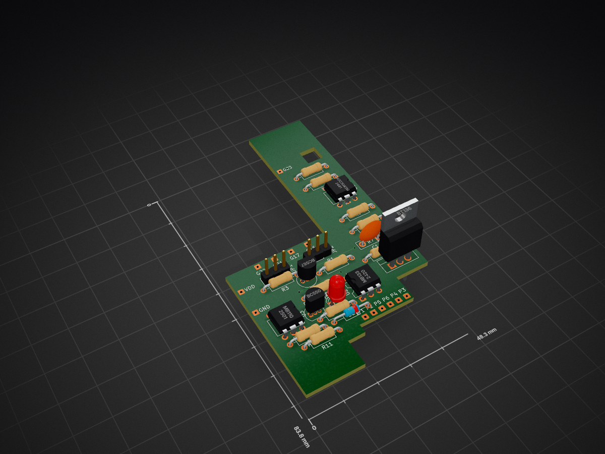
 mlauke/smartswitch1
sonnen battery controller based on ESP8266/ESP32 to drive a 3.3kW heater (Heißwasserspeicher-Einbauheizung) and integrates with the local hot water system.
Smartswitch is an open-source printed circuit board by mlauke, from the mlauke/smartswitch repository on GitHub, published under the MIT licence. It is a 2-layer board of 48.3 × 83.8 mm with 35 parts on 33 nets, routed with 115 tracks and 8 vias.
It is built around the BT136, MOC3042M and BC550, with the BC557 and G17 among its other parts. Its parts include 11 resistors, 6 connectors, 3 ICs, 3 transistors and 2 diodes. It belongs with the ESP32 and ESP8266 boards of this library.


DIY sonnen battery controller based on ESP8266/ESP32 to drive a 3.3kW heater (Heißwasserspeicher-Einbauheizung) and integrates with the local hot water system.

the software supports ESP8266 and ESP32 modules, which can be build for the appropriate target platform. releases can be found at https://github.com/mlauke/smartswitch/releases/
Install uv (https://docs.astral.sh/uv/concepts/tools/) and run proceed to source folder
cd smartswitch.espxx
# run tests
uv run pio test -e native
# run build
uv run pio run -e esp32 -e esp8266
# run check for outdated packages
uv run pio pkg outdatedthe reference implementation (at my home) uses the following components
The schematics and pcb is drawn with KiCad. The pcb uses a special layout which exactly matches the usable part of the ArduiBox's circuit board. KiCad files can be found here.


Although Triacs have very low Rs_on values in nowadays, they become very hot depending on the load to drive. Using a 3.3kW heater will require a big heatsink as can be seen in the calculation below.
Pmax = (Tj,max - Tamb,max) / Rth

I = P / U = 3300W / 230 V = 14,35A
Rs_on (BTA25) = 0,16 Ohm
P_loss = U * I = Rs_on * I * I
P_loss = 0,16 Ohm * (14,35 A)²
P_loss = 32,95W

R_max = (T_max - T_env) / P_loss
R_max = (120°C - 40°C) / 33W
R_max = 2,42K/W
R_heatsink = R_max - R_jc = 2,42K/W - 1,7K/W
R_heatsink = 0,7K/W !!!
... heatsink with <=0,7K/W makes no sense, because we will waste too much power wasted just for heating the environment and maybe would "blow up" the overall system design in terms of size and housing the components. therefore i decided to use a triac as switching device for a simple NO1 relais ("Schütz") which in turn will drive the load. the NO1 relais can directly placed next to the arduino case on our din rail.
as mentioned above, a SSR which can drive the 3,3kW load will become very hot if the load is switched on for longer heating periods. too hot to put the SSR together with the ESP controller board on a din rail inside of my houses fuse box.
| Qty | Value | Footprint | References |
|---|---|---|---|
| 2 | 39 | Resistor_THT:R_Axial_DIN0207_L6.3mm_D2.5mm_P10.16mm_Horizontal | R5, R9 |
| 2 | 4,7k | Resistor_THT:R_Axial_DIN0207_L6.3mm_D2.5mm_P10.16mm_Horizontal | R1, R3 |
| 2 | ~ | Connector_Wire:SolderWire-0.1sqmm_1x01_D0.4mm_OD1mm | P5, P6 |
| 1 | 0,01µ | Capacitor_THT:C_Disc_D7.5mm_W2.5mm_P5.00mm | C1 |
| 1 | 10k | Resistor_THT:R_Axial_DIN0207_L6.3mm_D2.5mm_P10.16mm_Horizontal | R2 |
| 1 | 120 | Resistor_THT:R_Axial_DIN0207_L6.3mm_D2.5mm_P10.16mm_Horizontal | R4 |
| 1 | 150 | Resistor_THT:R_Axial_DIN0207_L6.3mm_D2.5mm_P10.16mm_Horizontal | R11 |
| 1 | 1N914 | Diode_THT:D_DO-35_SOD27_P10.16mm_Horizontal | D2 |
| 1 | 1k | Resistor_THT:R_Axial_DIN0207_L6.3mm_D2.5mm_P10.16mm_Horizontal | R8 |
| 1 | 330 | Resistor_THT:R_Axial_DIN0207_L6.3mm_D2.5mm_P10.16mm_Horizontal | R7 |
| 1 | 360 | Resistor_THT:R_Axial_DIN0207_L6.3mm_D2.5mm_P10.16mm_Horizontal | R6 |
| 1 | 390k | Resistor_THT:R_Axial_DIN0207_L6.3mm_D2.5mm_P10.16mm_Horizontal | R10 |
| 1 | BC550 | Package_TO_SOT_THT:TO-92_Inline | Q3 |
| 1 | BC557 | Package_TO_SOT_THT:TO-92_Inline | Q1 |
| 1 | BT136 | Package_TO_SOT_THT:TO-220-3_Vertical | Q2 |
| 1 | DB | Connector_Wire:SolderWire-0.1sqmm_1x01_D0.4mm_OD1mm | P1 |
| 1 | G16 | Connector_Wire:SolderWire-0.1sqmm_1x01_D0.4mm_OD1mm | H4 |
| 1 | G17 | Connector_Wire:SolderWire-0.1sqmm_1x01_D0.4mm_OD1mm | H2 |
| 1 | G21 | Connector_Wire:SolderWire-0.1sqmm_1x01_D0.4mm_OD1mm | H3 |
| 1 | G22 | Connector_Wire:SolderWire-0.1sqmm_1x01_D0.4mm_OD1mm | H1 |
| 1 | G23 | Connector_Wire:SolderWire-0.1sqmm_1x01_D0.4mm_OD1mm | H5 |
| 1 | GND | Connector_Wire:SolderWire-0.1sqmm_1x01_D0.4mm_OD1mm | H6 |
| 1 | L | Connector_Wire:SolderWire-0.1sqmm_1x01_D0.4mm_OD1mm | P4 |
| 1 | LED | LED_THT:LED_D4.0mm | D1 |
| 1 | MB | Connector_Wire:SolderWire-0.1sqmm_1x01_D0.4mm_OD1mm | P2 |
| 1 | MB110 | Package_DIP:DIP-6_W7.62mm | U3 |
| 1 | MB133 | Package_DIP:DIP-6_W7.62mm | U2 |
| 1 | MOC3042M | Package_DIP:DIP-6_W7.62mm | U1 |
| 1 | P | Connector_Wire:SolderWire-0.1sqmm_1x01_D0.4mm_OD1mm | P3 |
| 1 | RX_Jmp | Connector_PinHeader_2.54mm:PinHeader_1x03_P2.54mm_Vertical | JP2 |
| 1 | TX_Jmp | Connector_PinHeader_2.54mm:PinHeader_1x03_P2.54mm_Vertical | JP1 |
| 1 | VDD | Connector_Wire:SolderWire-0.1sqmm_1x01_D0.4mm_OD1mm | H7 |
It measures 48.3 × 83.8 mm and has 2 copper layers, 1.6 mm thick.
35 parts, built around the BT136, MOC3042M, BC550 and BC557. The full list of its parts is on this page, with links to each part's symbol and footprint where PCBKit's library has them.
From the mlauke/smartswitch repository on GitHub, at the commit this page was made from: the board is kicad/SmartSwitch.kicad_pcb and its schematic kicad/SmartSwitch.kicad_sch. PCBKit opens the board in the browser, with nothing to install.
Its repository publishes it under the MIT licence: you may reuse it on that licence's terms (keep the author's notice, and for a copyleft licence share your changes alike).


ashloverscn/4ch-relay-1fan-arduino-nano-pcb
4ch-relay-1fan-arduino-nano-pcb


ashloverscn/4ch-spdt-relay-1fan-arduino-nano-pcb
4ch-spdt-relay-1fan-arduino-nano-pcb


ADFTech/xtec-uc-ip-main-pcb
KiCad hardware repo for the UC-IP main PCB (currently: IOB board family). This README documents the review-and-release process used to get a schematic/PCB change from an engineer's desk to fabrication.