

2 layers90 × 50 mm

 mlab-modules/REL1SW01
Dual MOSFET or single Relay switching module.
REL1SW01 is an open-source printed circuit board by mlab-modules, from the mlab-modules/REL1SW01 repository on GitHub. It is a 2-layer board of 30 × 40.1 mm with 22 parts on 18 nets, routed with 70 tracks and 0 vias.
It is built around the SS14 and IRLML6244. Its parts include 5 connectors, 4 resistors, 4 diodes, 2 capacitors and 1 crystal. It belongs with the home automation and IoT boards of this library.
The REL1SW01 is a versatile module from the MLAB series designed for triggering high current demaining devices (eg. high power led, high voltage circuits, DC motors, ..) using two N-MOSFET transistors or relay. It supports both bistable and monostable relay configurations and can be integrated into various electronic projects requiring relay switching or direct MOSFET control.
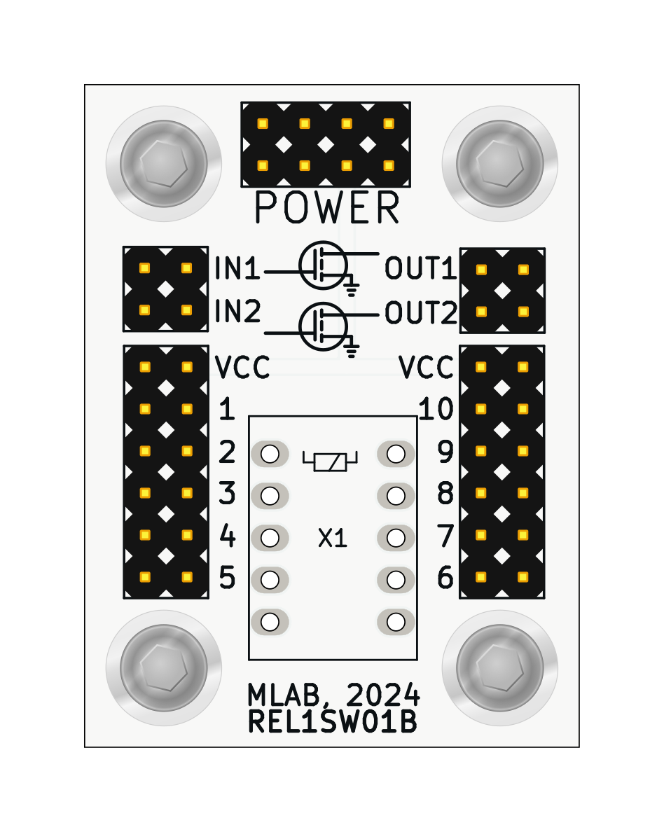
To configure the module for different uses:
| Qty | Value | Footprint | References |
|---|---|---|---|
| 4 | SROUB3M | Mlab_Mechanical:MountingHole_3mm | M1, M2, M3, M4 |
| 4 | SS14 | Diode_SMD:D_SMA | D1, D2, D3, D4 |
| 2 | 100R | Resistor_SMD:R_0805_2012Metric | R1, R2 |
| 2 | 100k | Resistor_SMD:R_0805_2012Metric | R3, R4 |
| 2 | HEADER_2x02_PARALLEL | Mlab_Pin_Headers:Straight_2x02 | J1, J2 |
| 2 | HEADER_2x06_PARALLEL | Mlab_Pin_Headers:Straight_2x06 | J3, J4 |
| 2 | IRLML6244 | Package_TO_SOT_SMD:SOT-23 | T1, T2 |
| 1 | 100nF | Capacitor_SMD:C_0805_2012Metric | C2 |
| 1 | 47uF | Capacitor_SMD:C_0805_2012Metric | C1 |
| 1 | HEADER_2x04_PARALLEL | Mlab_Pin_Headers:Straight_2x04 | J5 |
| 1 | RELE | Relay_THT:Relay_DPDT_FRT5 | X1 |
It measures 30 × 40.1 mm and has 2 copper layers, 1.6 mm thick.
22 parts, built around the SS14 and IRLML6244. The full list of its parts is on this page, with links to each part's symbol and footprint where PCBKit's library has them.
From the mlab-modules/REL1SW01 repository on GitHub, at the commit this page was made from: the board is hw/sch_pcb/REL1SW01.kicad_pcb and its schematic hw/sch_pcb/REL1SW01.kicad_sch. PCBKit opens the board in the browser, with nothing to install.
Its repository states no licence, so its author keeps all rights: ask mlab-modules before reusing the design.


0x23/nmWave-Interferometer
An Open Source Interferometer for Accurate Distance Measurements

fishpepper/tinyPEPPER
a tiny 16x16mm hole-to-hole 4in1 brushless ESC running BLHeli_s

aTaylor60/ESC_Frame
A combined frame and 4in1 brushless ESC running BLHeli_s with 16mm hole spacing

kaini/eink-clock
Source code and schematics for a clock using the ED060SC4 E-Ink display

tangles-0/cyberdeck-scout
// #ifndef PINPA0 // #define PINPA0 11 // #endif // #ifndef PINPA1 // #define PINPA1 8 // #endif // #ifndef PINPA2 // #define PINPA2 9 // #endif // #ifndef PINPA3 // #define PINPA3 10 // #endif // #ifndef PINPA4 //…

GabrielD98/PickUS_and_PlacUS
pick and place de PCB pour projet S4 de robotique