2 layers71.9 × 71.9 mm
 kaini/eink-clock11
Source code and schematics for a clock using the ED060SC4 E-Ink display
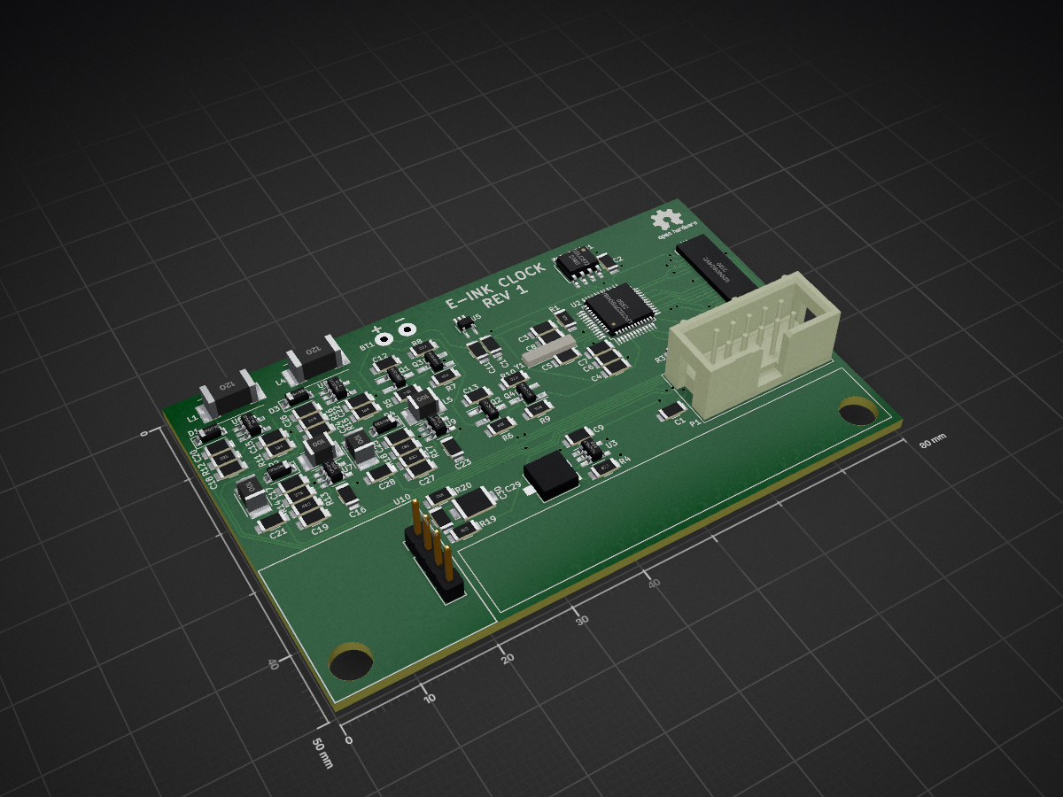
Eink clock is an open-source printed circuit board by kaini, from the kaini/eink-clock repository on GitHub, published under the MIT licence. It is a 2-layer board of 80 × 50 mm with 81 parts on 59 nets, routed with 687 tracks and 104 vias.
It is built around the LPC1227FBD48/301,1, LM2611BMF and TPS61041DBV, with the TS321ILT, 23LC512-E/P and TPS71533DCKR-TP among its other parts. Its parts include 30 capacitors, 20 resistors, 10 ICs, 6 inductors and 4 diodes. It belongs with the lEDs and displays boards and the NXP (LPC, Kinetis, i.MX RT) boards of this library.


For details read the articles on my website.
To be able to successfully build the project you need the inkscape and
magick executable and a ARM GCC toolchain in your path. The resulting binary
is ready to be flashed onto the controller.
cd timekeeper
xargo build --target lpc1227-none-eabi --release
To execute the tests, run cargo test.
There are some features you might want to activate.
semihosted: Enable debug output via the semihosting mechanism.fake_time: Do not wait for a valid DCF77 time, but just assume a hardcoded time value.stay_awake: Panic instead of going into Deep Power-Down mode.The PCB layout is not up to date!
| Qty | Value | Footprint | References |
|---|---|---|---|
| 11 | 100n | Resistors_SMD:R_0805_HandSoldering | C1, C2, C3, C6, C7, C9, C10, C11, C12, C13, C30 |
| 4 | 100k | Resistors_SMD:R_0805_HandSoldering | R5, R6, R7, R9 |
| 4 | 10µ | einkclock:Inductor_TAIYO_YUDEN_3225 | L2, L3, L5, L6 |
| 4 | 1µ | Resistors_SMD:R_0805_HandSoldering | C17, C20, C25, C26 |
| 4 | 22µ | Resistors_SMD:R_0805_HandSoldering | C16, C21, C23, C28 |
| 4 | MBR0530 | Diodes_SMD:D_SOD-123 | D1, D2, D3, D4 |
| 3 | 10k | Resistors_SMD:R_0805_HandSoldering | R1, R2, R3 |
| 3 | 22p | Resistors_SMD:R_0805_HandSoldering | C5, C8, C18 |
| 3 | 4.7µ | Resistors_SMD:R_0805_HandSoldering | C4, C15, C22 |
| 2 | 12µ | einkclock:Bourns_Inductor_SDR0703 | L1, L4 |
| 2 | 1k | Resistors_SMD:R_0805_HandSoldering | R19, R20 |
| 2 | 2.2k | Resistors_SMD:R_0805_HandSoldering | R8, R10 |
| 2 | 330p | Resistors_SMD:R_0805_HandSoldering | C19, C27 |
| 2 | BSH205 | TO_SOT_Packages_SMD:SOT-23_Handsoldering | Q1, Q2 |
| 2 | IRLML6244 | TO_SOT_Packages_SMD:SOT-23_Handsoldering | Q3, Q4 |
| 2 | LM2611 | TO_SOT_Packages_SMD:SOT-23-5_HandSoldering | U7, U9 |
| 2 | MountingHole_5mm | Mounting_Holes:MountingHole_5mm | , |
| 2 | TPS61041 | TO_SOT_Packages_SMD:SOT-23-5_HandSoldering | U6, U8 |
| 1 | 100µ | Resistors_SMD:R_1206_HandSoldering | C29 |
| 1 | 10k | Potentiometers:Potentiometer_Trimmer_Vishay_TS53YL | RV1 |
| 1 | 130k | Resistors_SMD:R_0805_HandSoldering | R11 |
| 1 | 16p | Resistors_SMD:R_0805_HandSoldering | C24 |
| 1 | 180k | Resistors_SMD:R_0805_HandSoldering | R15 |
| 1 | 2.2M | Resistors_SMD:R_0805_HandSoldering | R12 |
| 1 | 23LC512 | Housings_SOIC:SOIC-8_3.9x4.9mm_Pitch1.27mm | U1 |
| 1 | 2M | Resistors_SMD:R_0805_HandSoldering | R16 |
| 1 | 3.16k | Resistors_SMD:R_0805_HandSoldering | R14 |
| 1 | 3.83k | Resistors_SMD:R_0805_HandSoldering | R18 |
| 1 | 32.768k 12.5p | einkclock:Crystal_Lying_1 | Y1 |
| 1 | 43k | Resistors_SMD:R_0805_HandSoldering | R17 |
| 1 | 470n | Resistors_SMD:R_0805_HandSoldering | C14 |
| 1 | 47k | Resistors_SMD:R_0805_HandSoldering | R4 |
| 1 | 48.7k | Resistors_SMD:R_0805_HandSoldering | R13 |
| 1 | 6.4-4 | Wire_Connections_Bridges:WireConnection_1.00mmDrill | BT1 |
| 1 | DCF77_Generic | einkclock:Reichelt_DCF77_Module | U10 |
| 1 | ED060SC4V2 | einkclock:Hirose_FH26-39S-0.3SHW | U4 |
| 1 | LPC1227FBD48/301 | Housings_QFP:LQFP-48_7x7mm_Pitch0.5mm | U2 |
| 1 | OSHW-Logo2_7.3x6mm_SilkScreen | Symbols:OSHW-Logo2_7.3x6mm_SilkScreen | |
| 1 | SWD | Connectors:IDC_Header_Straight_10pins | P1 |
| 1 | TPS71533DCKR | TO_SOT_Packages_SMD:SOT-353_SC-70-5_Handsoldering | U5 |
| 1 | TS321ILT | TO_SOT_Packages_SMD:SOT-23-5_HandSoldering | U3 |
It measures 80 × 50 mm and has 2 copper layers, 1.6 mm thick.
81 parts, built around the LPC1227FBD48/301,1, LM2611BMF, TPS61041DBV and TS321ILT. The full list of its parts is on this page, with links to each part's symbol and footprint where PCBKit's library has them.
From the kaini/eink-clock repository on GitHub, at the commit this page was made from: the board is kicad/einkclock.kicad_pcb. PCBKit opens the board in the browser, with nothing to install.
Its repository publishes it under the MIT licence: you may reuse it on that licence's terms (keep the author's notice, and for a copyleft licence share your changes alike).


cva68/ESPBreadboardRobot
Peripheral and breakout board for the ESP-32, with firmware designed for use with Microsoft MakeCode

OberTechniks/LPS
DIY Lab Power Supply with adjustable voltage and current limiting


benklop/screen-adapter
This directory contains documentation and configuration files for supporting a 720x720 DSI display with FL7707N controller.

Calculinux/DSI-screen-adapter
An adapter to use a 4 inch DSI display in the picocalc with the Luckfox Lyra