2 layers53.8 × 28.5 mm
MSPMO
adityajoshi2008/MSPM0-DevKit
🌐 ARM Cortex-M0+ • KiCad 10.0 • Open Source • PCB Hardware
38 partsMIT
 MikhalevDima/MSPM0-TutorialPCB
Учебный проект, двухслойной печатной платы. Спроектированная в KiCad.
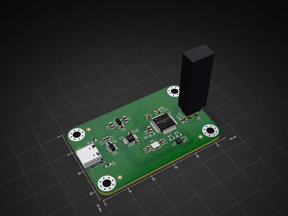
MSPM0-TutorialPCB is an open-source printed circuit board by MikhalevDima, from the MikhalevDima/MSPM0-TutorialPCB repository on GitHub. It is a 2-layer board of 55 × 34 mm with 37 parts on 61 nets, routed with 327 tracks and 77 vias.
It is built around the MSPM0G3507SPTR, CH340E and LIS2DH, with the SPX3819M5-L-3-3, USB4105-GF-A and USBLC6-2SC6 among its other parts. Its parts include 14 capacitors, 8 resistors, 4 ICs, 2 connectors and 1 diode.


Двухслойная печатная плата (PCB), спроектированная в KiCad с использованием методологии и лучших практик инженерного канала Phil's Lab.
В процессе разработки этого устройства были применены следующие практики:
GND) для снижения помех, настроены корректные тепловые барьеры (Thermal Reliefs) для падов./hardware — исходные файлы проекта KiCad (.kicad_sch, .kicad_pcb)./production — итоговый пакет для завода:
gerbers/ — файлы слоев в формате Gerber и файлы сверловки (.drl).bom/ — ведомость материалов (BOM) в формате CSV для закупки.position/ — файлы координат (.pos) для робота-установщика SMD./docs — принципиальная схема в формате PDF для быстрого просмотра (без необходимости открывать САПР).Проект разработан в учебных целях для демонстрации навыков проектирования современных печатных плат.
| Qty | Value | Footprint | References |
|---|---|---|---|
| 9 | 470n | Capacitor_SMD:C_0603_1608Metric | C2, C3, C5, C7, C8, C9, C10, C13, C14 |
| 5 | 5k1 | Resistor_SMD:R_0603_1608Metric | R2, R3, R5, R6, R7 |
| 4 | M3 | MountingHole:MountingHole_3.2mm_M3_Pad_Via | MH1, MH2, MH3, MH4 |
| 3 | 10u | Capacitor_SMD:C_0805_2012Metric | C1, C4, C6 |
| 3 | Fiducial | Fiducial:Fiducial_1mm_Mask2mm | FID1, FID2, FID3 |
| 2 | 0R | Resistor_SMD:R_0603_1608Metric | R1, R8 |
| 2 | 15p | Capacitor_SMD:C_0603_1608Metric | C11, C12 |
| 1 | 100k | Resistor_SMD:R_0603_1608Metric | R4 |
| 1 | 8MHz | Crystal:Crystal_SMD_3225-4Pin_3.2x2.5mm | X1 |
| 1 | CH340E | Package_SO:MSOP-10_3x3mm_P0.5mm | U4 |
| 1 | LIS2DH | Package_LGA:LGA-14_2x2mm_P0.35mm_LayoutBorder3x4y | U3 |
| 1 | MSPM0G3507SPTR | Package_QFP:LQFP-48_7x7mm_P0.5mm | U2 |
| 1 | SPX3819M5-L-3-3 | Package_TO_SOT_SMD:SOT-23-5 | U1 |
| 1 | TC2030 | Connector:Tag-Connect_TC2030-IDC-FP_2x03_P1.27mm_Vertical | J2 |
| 1 | USB4105-GF-A | Connector_USB:USB_C_Receptacle_GCT_USB4105-xx-A_16P_TopMnt_Horizontal | J1 |
| 1 | USBLC6-2SC6 | Package_TO_SOT_SMD:SOT-23-6 | D1 |
It measures 55 × 34 mm and has 2 copper layers, 1.6 mm thick.
37 parts, built around the MSPM0G3507SPTR, CH340E, LIS2DH and SPX3819M5-L-3-3. The full list of its parts is on this page, with links to each part's symbol and footprint where PCBKit's library has them.
From the MikhalevDima/MSPM0-TutorialPCB repository on GitHub, at the commit this page was made from: the board is hardware/MSPM0-TutorialPCB.kicad_pcb and its schematic hardware/MSPM0-TutorialPCB.kicad_sch. PCBKit opens the board in the browser, with nothing to install.
Its repository states no licence, so its author keeps all rights: ask MikhalevDima before reusing the design.
adityajoshi2008/MSPM0-DevKit
🌐 ARM Cortex-M0+ • KiCad 10.0 • Open Source • PCB Hardware

basillx1/mspm0-accelerometer-board
2-layer KiCad board: TI MSPM0 MCU + LIS2DH accelerometer, USB-C, SWD debug

benbruder/MSPM0
Design of schematic and PCB for a TI MSPM0-based MCU with all of its components.

ctrl-z3d/pcb-designs
A personal archive of PCB projects I've designed and built along the way. Schematics, board layouts, manufacturing files, and notes.

hykoser/LIS2DH-Accelerometer-Board
A custom accelerometer development board designed with KiCad and MSPM0 microcontroller.

prashantbhandary/mspmo-baord
A compact USB-C development board for TI's MSPM0G3507 (Arm Cortex-M0+, 80 MHz, 128 KB flash, 32 KB SRAM), with an on-board USB-to-UART bridge, a 3-axis accelerometer and a Tag-Connect SWD footprint.

