
2 layers58 × 37.1 mm
Phils Lab #165
ctrl-z3d/pcb-designs
A personal archive of PCB projects I've designed and built along the way. Schematics, board layouts, manufacturing files, and notes.
37 parts1

 hykoser/LIS2DH-Accelerometer-Board1
A custom accelerometer development board designed with KiCad and MSPM0 microcontroller.
IVME OLCER is an open-source printed circuit board by hykoser, from the hykoser/LIS2DH-Accelerometer-Board repository on GitHub. It is a 2-layer board of 54.1 × 31.8 mm with 37 parts on 61 nets, routed with 380 tracks and 120 vias.
It is built around the MSPM0G3507SPTR, CH340E and LIS2DH, with the SPX3819M5-L-3-3 and USBLC6-2SC6 among its other parts. Its parts include 14 capacitors, 8 resistors, 5 ICs, 2 connectors and 1 crystal. It belongs with the sensors and measurement and microcontroller boards boards of this library.


A custom-designed breakout and development board for the LIS2DH 3-axis MEMS accelerometer. This project was developed to provide a reliable hardware interface for embedded system applications.
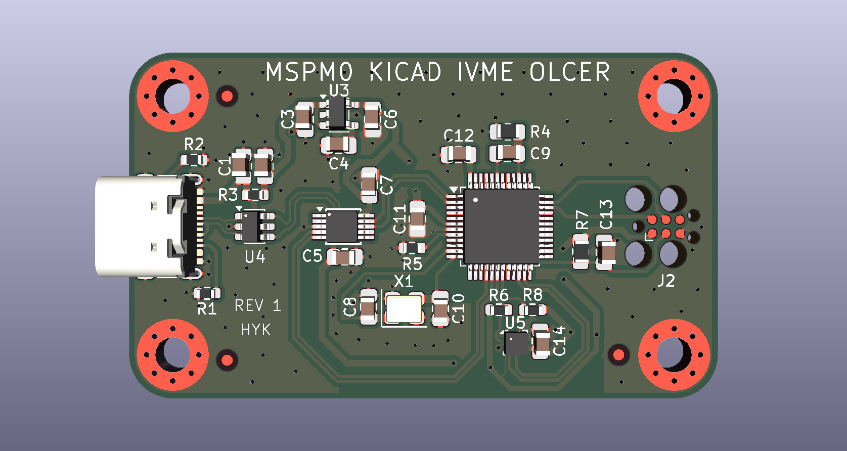
.kicad_pro, .kicad_pcb, .kicad_sch) for editing and modification..zip archive containing standard Gerber and Drill files.To fabricate this board, simply download the Gerber .zip file from this repository and upload it directly to your preferred PCB manufacturer (such as JLCPCB or PCBWay).
Designed by Halis Yiğit Koşer

| Qty | Value | Footprint | References |
|---|---|---|---|
| 9 | 470nF | Capacitor_SMD:C_0805_2012Metric_Pad1.18x1.45mm_HandSolder | C1, C2, C4, C5, C7, C9, C12, C13, C14 |
| 4 | 5K1 | Resistor_SMD:R_0603_1608Metric | R1, R2, R6, R8 |
| 4 | MountingHole_Pad | MountingHole:MountingHole_3.2mm_M3_Pad_Via | H1, H2, H3, H4 |
| 3 | 10uF | Capacitor_SMD:C_0805_2012Metric_Pad1.18x1.45mm_HandSolder | C3, C6, C11 |
| 3 | Fiducial | Fiducial:Fiducial_1mm_Mask2mm | FID1, FID2, FID3 |
| 2 | 15pF | Capacitor_SMD:C_0805_2012Metric_Pad1.18x1.45mm_HandSolder | C8, C10 |
| 1 | 0R | Resistor_SMD:R_0603_1608Metric | R3 |
| 1 | 0R | Resistor_SMD:R_0805_2012Metric_Pad1.20x1.40mm_HandSolder | R4 |
| 1 | 100K | Resistor_SMD:R_0603_1608Metric | R5 |
| 1 | 5K1 | Resistor_SMD:R_0805_2012Metric_Pad1.20x1.40mm_HandSolder | R7 |
| 1 | 8MHz | Crystal:Crystal_SMD_3225-4Pin_3.2x2.5mm | X1 |
| 1 | CH340E | Package_SO:MSOP-10_3x3mm_P0.5mm | U2 |
| 1 | Conn_ARM_SWD_TagConnect_TC2030 | Connector:Tag-Connect_TC2030-IDC-FP_2x03_P1.27mm_Vertical | J2 |
| 1 | LIS2DH | Package_LGA:LGA-14_2x2mm_P0.35mm_LayoutBorder3x4y | U5 |
| 1 | MSPM0G3507SPTR | Package_QFP:LQFP-48_7x7mm_P0.5mm | U1 |
| 1 | SPX3819M5-L-3-3 | Package_TO_SOT_SMD:SOT-23-5 | U3 |
| 1 | USBLC6-2SC6 | Package_TO_SOT_SMD:SOT-23-6 | U4 |
| 1 | USB_C_Receptacle_USB2.0_16P | Connector_USB:USB_C_Receptacle_GCT_USB4105-xx-A_16P_TopMnt_Horizontal | J1 |
It measures 54.1 × 31.8 mm and has 2 copper layers, 1.6 mm thick.
37 parts, built around the MSPM0G3507SPTR, CH340E, LIS2DH and SPX3819M5-L-3-3. The full list of its parts is on this page, with links to each part's symbol and footprint where PCBKit's library has them.
From the hykoser/LIS2DH-Accelerometer-Board repository on GitHub, at the commit this page was made from: the board is KiCad_Files/IVME_OLCER.kicad_pcb and its schematic KiCad_Files/IVME_OLCER.kicad_sch. PCBKit opens the board in the browser, with nothing to install.
Its repository states no licence, so its author keeps all rights: ask hykoser before reusing the design.
ctrl-z3d/pcb-designs
A personal archive of PCB projects I've designed and built along the way. Schematics, board layouts, manufacturing files, and notes.

prashantbhandary/mspmo-baord
A compact USB-C development board for TI's MSPM0G3507 (Arm Cortex-M0+, 80 MHz, 128 KB flash, 32 KB SRAM), with an on-board USB-to-UART bridge, a 3-axis accelerometer and a Tag-Connect SWD footprint.

adityajoshi2008/MSPM0-DevKit
🌐 ARM Cortex-M0+ • KiCad 10.0 • Open Source • PCB Hardware


basillx1/mspm0-accelerometer-board
2-layer KiCad board: TI MSPM0 MCU + LIS2DH accelerometer, USB-C, SWD debug

benbruder/MSPM0
Design of schematic and PCB for a TI MSPM0-based MCU with all of its components.


cashmoneyisaac/mspm0-microcontroller-pcb
a two-layer ti mspm0g3507 board with usb-c, usb-to-uart, swd, and an i²c accelerometer. includes kicad source and manufacturing files.