

4 layers66 × 90 mm

 mikagosz/FanCtrl3
USB-powered controller for three 4-pin PWM fans, driven by the CPU temperature of a Proxmox VE host - KiCad, MicroPython, OpenSCAD
FanCtrl3-Pro is an open-source printed circuit board by mikagosz, from the mikagosz/FanCtrl3 repository on GitHub, published under the MIT licence. It is a 2-layer board of 90 × 60 mm with 39 parts on 46 nets, routed with 993 tracks and 120 vias.
It is built around the LM27313XMF, DS18B20 and TPS2553DBV, with the SS14 among its other parts. Its parts include 16 resistors, 7 capacitors, 4 connectors, 3 ICs and 3 transistors. It belongs with the RP2040 boards of this library.


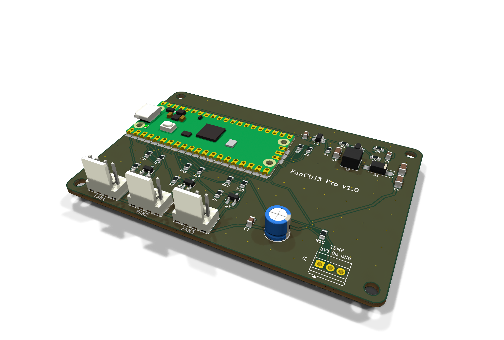
A USB-powered controller for three 4-pin PWM fans, driven by the CPU temperature of a Proxmox VE host.
One USB cable to the host is all it needs — power, control and fan speed readings all go over it. The fan curve runs inside the controller, so a host reboot, a crashed service or a pulled cable never leaves the fans stopped.




Designed for small home servers and mini PCs running Proxmox: the machine sits in a closed cabinet, its own fan is not enough for the cabinet, and a set of quiet 120 mm fans should spin up only when the server actually works.
[!NOTE] FanCtrl3 is a hobby project, built in spare time. Updates may not come often — but ideas, questions and build reports are always welcome (see Contact and contributions).
[!WARNING] FanCtrl3 has not been tested on real hardware yet. Hardware testing is coming soon; this section will be updated with the results. Until the first boards have run for a while, treat this as a reviewed design, not a proven product.
| Area | How | Result |
|---|---|---|
| Schematics | KiCad ERC, both variants | 0 errors, 0 warnings |
| Pro PCB | KiCad DRC with schematic parity | 0 violations, 0 unconnected pads, 0 parity issues |
| Lite perfboard | the generator's own checker | every net connected, no hole shared by two nets, no wire through a foreign pad, no overlapping parts |
| Enclosure | intersection of the enclosure with the component bodies | 0 collisions, both variants |
| Control logic | 22 unit tests, run under CPython and MicroPython | all pass |
Firmware main.py | runs under the MicroPython unix port on stubbed hardware: replies, 25 kHz inverted PWM, watchdog; SERVICE and service mode; SAVE success and failure (12 checks) | all pass |
| Host daemon and CLI | 10 unit tests (Intel and AMD sensors, several CPU packages, CLI errors, a silent socket client) and 13 end-to-end tests against a simulated controller: sensor selection, curve, status, send, calibrate (incl. a dead fan and failsafe), clean stop, restart without a temperature, crash → failsafe | all pass |
Every push and pull request runs these tests on GitHub Actions.
FAULT signal, real fan speeds from the tachometers, the DS18B20 probe, the LED,
the watchdog, USB behaviour with and without a host.2e8a:0005 is MicroPython's default ID).k10temp, zenpower) is tested only against simulated sensors so
far — a report from a real AMD host is welcome.tests/test_main_smoke.sh depends on timing and can fail on a heavily loaded
machine; run it again before looking for a bug.calibrate command that
measures it.| FanCtrl3 Lite | FanCtrl3 Pro | |
|---|---|---|
| Build | modules on a 72 × 47 mm perfboard (SCI PC-3) | custom 2-layer PCB, 90 × 60 mm |
| Soldering | through-hole only (plus one SOT-23-6 on an adapter) | 0805/1206 and SOT-23 by hand, no QFN |
| 12 V | Pololu U3V16F12 module | TI LM27313 boost on the board (12.4 V) |
| PWM output | BC547B, open collector | 2N7002, open drain |
| Current limit | TPS2553 on a SparkFun SOT-23 → DIP adapter | TPS2553 on the board |
| Pico | in sockets, removable | soldered flat |
| Build guide | docs/build-lite.md | docs/build-pro.md |
Both use the same pinout and run the same firmware.
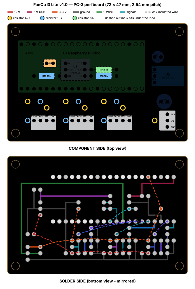 Lite — perfboard wiring drawing | 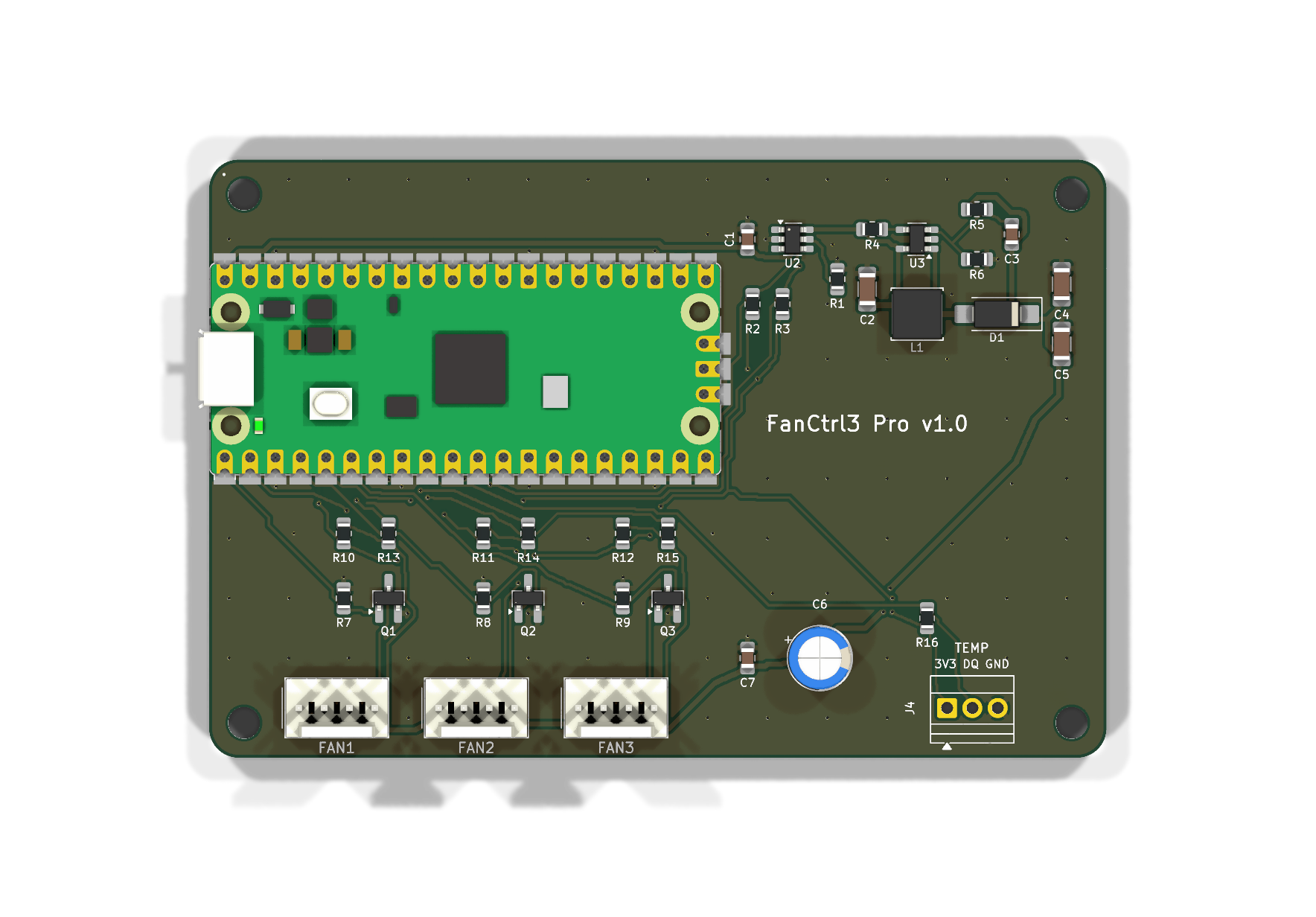 Pro — PCB, top |
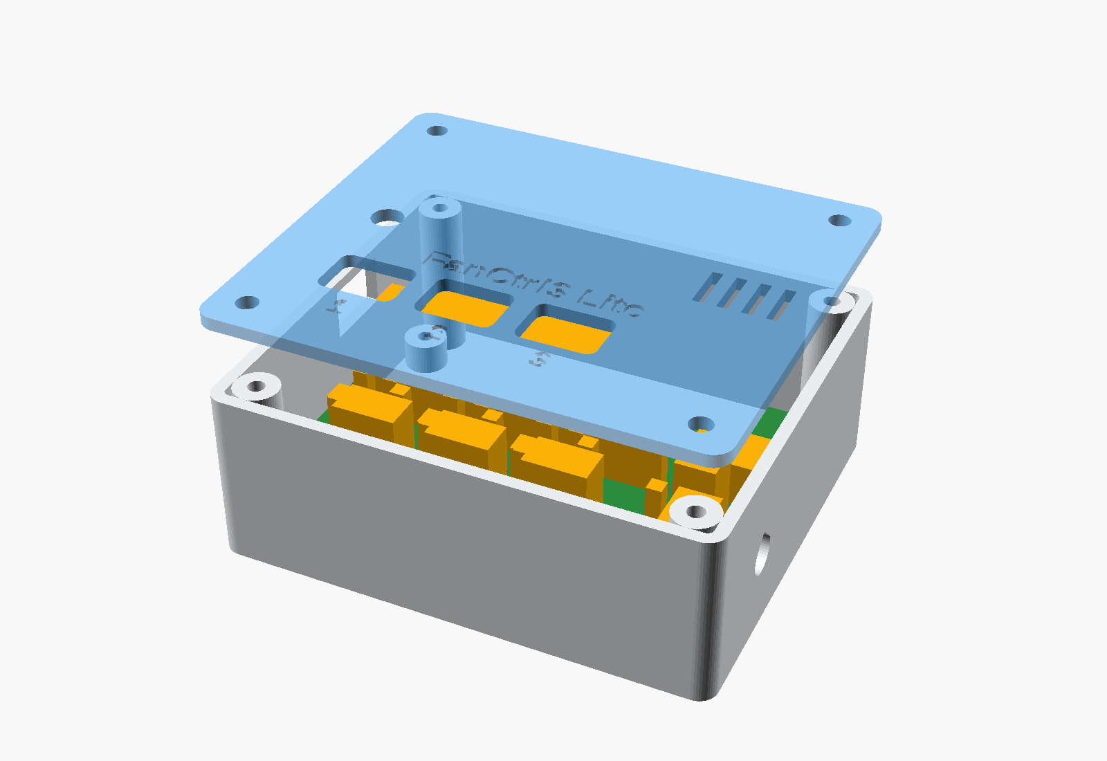 Lite — enclosure | 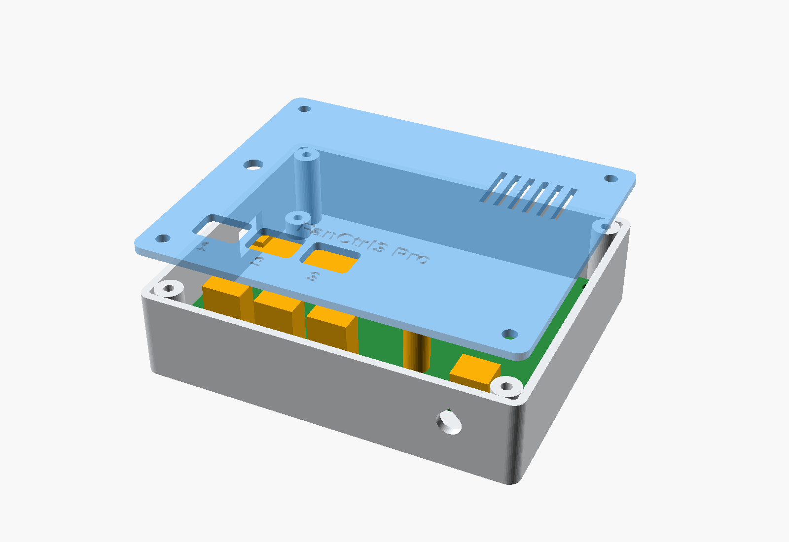 Pro — enclosure |
 Proxmox host                                 FanCtrl3
┌────────────────────────┐   USB cable    ┌──────────────────────────────────────┐
│ CPU temp ─► fanctl     │  power + data  │ Pico: curve, hysteresis, failsafe    │
│             daemon ────┼───────────────►│  ├─ PWM ×3 ──► open collector/drain  │
│  TEMP 54.0 every 5 s   │◄───────────────│  ├─ tach ×3 ◄── fans                 │
│  STATUS, alarms        │                │  └─ DS18B20 ◄── ambient probe        │
└────────────────────────┘                │                                      │
                                          │ VBUS ─► TPS2553 ─► 12V boost ─► fans │
                                          │         (≈0.5 A)                     │
                                          └──────────────────────────────────────┘
The link is plain text over USB CDC — TEMP 54.0, STATUS, SET 1 40 — so it can
be driven by hand from any terminal. Full protocol: docs/firmware.md.
The whole controller lives on one USB 2.0 port, which is allowed to supply 500 mA. The design is sized for three low-power 120 mm PWM fans rated at up to 0.6 W each (for example Noctua NF-P12 redux-1300 PWM):
3 × 0.6 W = 1.8 W at 12 V → ÷ 0.85 converter efficiency + ≈ 0.15 W for the Pico ≈ 0.45 A from the port.
[!CAUTION] Fans rated above 0.6 W each will not fit this budget. The TPS2553 limits the fan side to 465–570 mA and reports
FAULT, but the fans will not reach full speed. Check the rated input power of your fans before you build.
RPI_PICO, then firmware/flash.sh.sh host/install.sh # as root on the Proxmox host
fanctl status
fanctl calibrate # finds the lowest duty each fan still spins at| Path | What is inside |
|---|---|
hardware/tools/ | generators — the design lives in code: design_pro.py and design_lite.py are the single source of truth |
hardware/pro/ | KiCad project of the Pro PCB, schematic PDF, fabrication/ Gerbers + drill ZIP and BOM, preview/ 3D renders |
hardware/lite/ | Lite schematic (KiCad + PDF), perfboard drawing (SVG) and wiring table |
hardware/enclosure/ | parametric OpenSCAD enclosure and ready STL files for both variants |
firmware/ | MicroPython for the Pico: logic.py (no hardware, testable) and main.py (pins) |
host/ | fanctl daemon and CLI, udev rule, systemd unit, installer |
sim/ | the controller on a pseudo-terminal, for testing the host side without hardware |
tests/ | everything that runs without hardware: tests/run_all.sh |
docs/ | documentation |
fanctlIdeas, improvements, a better circuit, a build report or a question — all welcome. Open an issue on this repository or write to support@fractal8.eu. See CONTRIBUTING.md.
FanCtrl3 is built in spare time. If it is useful to you, you can support its development through GitHub Sponsors — it helps pay for parts and prototype boards.
MIT — see LICENSE. This covers the hardware design files, the firmware and the host software.
| Qty | Value | Footprint | References |
|---|---|---|---|
| 5 | 10k | Resistor_SMD:R_0805_2012Metric_Pad1.20x1.40mm_HandSolder | R2, R6, R13, R14, R15 |
| 4 | 100k | Resistor_SMD:R_0805_2012Metric_Pad1.20x1.40mm_HandSolder | R3, R7, R8, R9 |
| 4 | 4k7 | Resistor_SMD:R_0805_2012Metric_Pad1.20x1.40mm_HandSolder | R10, R11, R12, R16 |
| 4 | M3 | MountingHole:MountingHole_3.2mm_M3 | H1, H2, H3, H4 |
| 3 | 10u 25V | Capacitor_SMD:C_1206_3216Metric_Pad1.33x1.80mm_HandSolder | C2, C4, C5 |
| 3 | 2N7002 | Package_TO_SOT_SMD:SOT-23_Handsoldering | Q1, Q2, Q3 |
| 2 | 100n | Capacitor_SMD:C_0805_2012Metric_Pad1.18x1.45mm_HandSolder | C1, C7 |
| 2 | 51k | Resistor_SMD:R_0805_2012Metric_Pad1.20x1.40mm_HandSolder | R1, R4 |
| 1 | 100u 25V | Capacitor_THT:CP_Radial_D6.3mm_P2.50mm | C6 |
| 1 | 10u | Inductor_SMD:L_Changjiang_FNR5040S | L1 |
| 1 | 220p | Capacitor_SMD:C_0805_2012Metric_Pad1.18x1.45mm_HandSolder | C3 |
| 1 | 91k | Resistor_SMD:R_0805_2012Metric_Pad1.20x1.40mm_HandSolder | R5 |
| 1 | DS18B20 | TerminalBlock:TerminalBlock_Xinya_XY308-2.54-3P_1x03_P2.54mm_Horizontal | J4 |
| 1 | FAN1 | Connector_Molex:Molex_KK-254_AE-6410-04A_1x04_P2.54mm_Vertical | J1 |
| 1 | FAN2 | Connector_Molex:Molex_KK-254_AE-6410-04A_1x04_P2.54mm_Vertical | J2 |
| 1 | FAN3 | Connector_Molex:Molex_KK-254_AE-6410-04A_1x04_P2.54mm_Vertical | J3 |
| 1 | LM27313XMF | Package_TO_SOT_SMD:SOT-23-5_HandSoldering | U3 |
| 1 | Raspberry Pi Pico | Module:RaspberryPi_Pico_SMD_HandSolder | U1 |
| 1 | SS14 | Diode_SMD:D_SMA_Handsoldering | D1 |
| 1 | TPS2553DBV | Package_TO_SOT_SMD:SOT-23-6_Handsoldering | U2 |
It measures 90 × 60 mm and has 2 copper layers, 1.6 mm thick.
39 parts, built around the LM27313XMF, DS18B20, TPS2553DBV and SS14. The full list of its parts is on this page, with links to each part's symbol and footprint where PCBKit's library has them.
From the mikagosz/FanCtrl3 repository on GitHub, at the commit this page was made from: the board is hardware/pro/FanCtrl3-Pro.kicad_pcb and its schematic hardware/lite/FanCtrl3-Lite.kicad_sch. PCBKit opens the board in the browser, with nothing to install.
Its repository publishes it under the MIT licence: you may reuse it on that licence's terms (keep the author's notice, and for a copyleft licence share your changes alike).

heresiarch/esp32-wifi-eth-gateway
This is proof of concept of a Wifi to Ethernet Gateway with ESP32


calicopizzadelivery/sbc-development-baseboard
Baseboard for remote management of an attached SBC: K64 MCU as USB HID to the target and Ethernet to the workstation, six switched USB-A ports, isolated SPDT relays, level-shifted console, switched target power


ssbingo/samba-solar-track
Samba Solar Track – Solarnachführung mit Sturmschutz: Handbuch, Platine und Gehäuse für den Nachbau (10,1-Zoll-Version)

xdylanm/modular-system-psu
A PSU for a modular Eurorack system, featuring +/-12V and 5V rails, USB-C input, and a regulated USB-A output.

microdynamics-robot-quadcopter/breeze_electronics_design
This project is created and managed by EDA softwares, which contains the breeze quadcopter's component library, footprint library, schematic, printed circuit boards, etc.