
2 layers87.6 × 100.8 mm
EtherKraken
karmakrafts/EtherKraken
A RP3A0 SiP based controller with 34 programmable IOs, Cortex M0 co-processor, 2MB of flash, SPI, I²C, UART and 100Base-T connectivity.
84 parts3Apache-2.0

 mihranrazaa/Knobble
A modern design for not so common radios
BetterNat is an open-source printed circuit board by mihranrazaa, from the mihranrazaa/Knobble repository on GitHub, published under the MIT licence. It is a 2-layer board of 66.7 × 88.1 mm with 7 parts on 51 nets, routed with 119 tracks and 1 via.
It is built around the RASPBERRY PI ZERO 2 W. Its parts include 3 switches and 2 ICs. It belongs with the radio and wireless boards and the Raspberry Pi (Linux) boards of this library.
A modern design for not so common radios.
Knobble is a Rasberry pi based portable Radio scanning system design for real time monitoring and interacting with different radio frequncies via an RTL-SDR dongle. It can help you to listen through FM, aviation, emergency, amateur, and public service frequencies.
| Control | Action |
|---|---|
| Rotate Encoder | Adjust volume or frequency |
| Encoder Button (tap) | Start/stop scanning |
| Encoder Button (hold) | Toggle mute/unmute |
| Switch 1 | Cycle through preset banks |
| Switch 2 | Toggle scan mode (Manual / Auto / Preset) |
| Switch 3 | Change radio service type (FM, Aviation, etc.) |
The files for the PCB and Schematics are available in the PCB folder and gerber files are added in the Production folder..
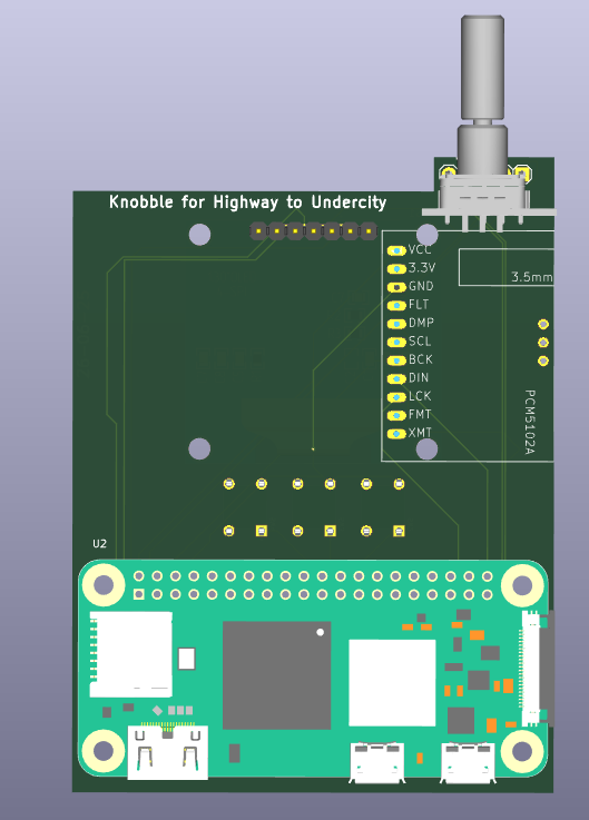
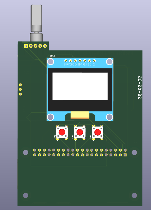
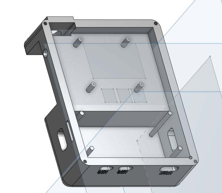
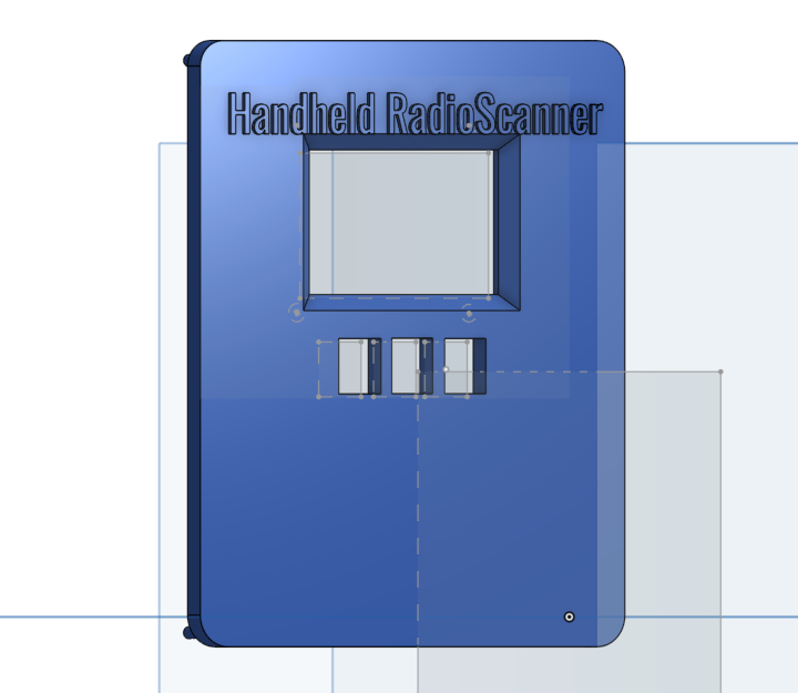
The step files for the keyboard are available in the CAD folder and also in the Production Folder.
BASE
TOP
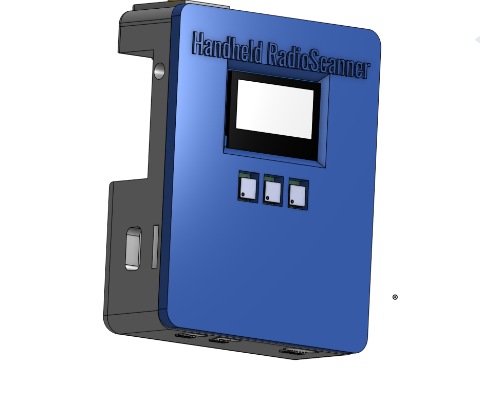
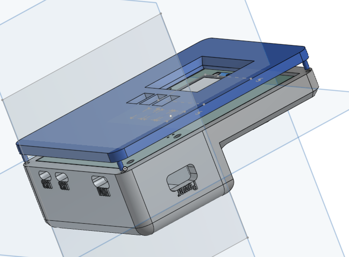
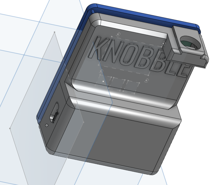
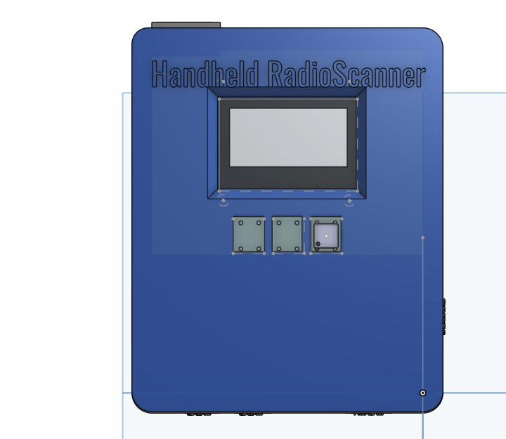
Can't add a combine image of pcb with components my laptop can't handle all that together.. Other than this you just have to purchase the Components given in the BOM and solder and assemble them.
| Component | Quantity | Note | Price | Link |
|---|---|---|---|---|
| Rasberry pi zero 2 w | 1 | Controlling UNIT | 16USD | Available |
| RTL-SDR | 1 | most important for the project.. | 51USD | Available |
| 1.3 inch oled display | 1 | It has 2 extra Stabilizers just in case.. | 12USD | Available |
| macro switches | 3 | user input they are 50 pcs the link i have provided | 0.9USD | Available |
| Rotary encoder | 1 | User input | 0.9USD | Available |
| PCM5102A DAC | 1 | For connecting external speaker, headphones, etc | 26USD | Available |
| UPS Hat | 1 | For portability | 26USD | Available |
| PCB | ** | JLCPCB ftw | - | |
| CAD | ** | Legion ftw | - | |
| Total | 135-145USD |
I know it going above 150USD so i'm ready to pay the remaining cost...
Going to Undercity!! and i always wanted to build thiss project becuase RF always makes me curious it is like another invisible world which we can only access through speacial gears feels Magical...
Building the custom case.. i don't have the words to express my pain...
Check my BLOG ~ mihranrazaa(If you are reading this please review HappyUSB too ToT )
BYEEE
| Qty | Value | Footprint | References |
|---|---|---|---|
| 3 | 1825910-6 | Switch:SW_1825910-6-43D | SW2, SW3, SW4 |
| 1 | KY-040 | Ky0:KY-040-PORT3D | U1 |
| 1 | OLED_128X64_1.3_I2C | Oled:LCD_OLED_128X64_1.3_I2C3D | DS1 |
| 1 | RASPBERRY_PI_ZERO_2_W | 2w:MODULE_RASPBERRY_PI_ZERO_2_W3d | U2 |
| 1 | ~ | dac:PCM5102A-AMZN-BOARD | 1 |
karmakrafts/EtherKraken
A RP3A0 SiP based controller with 34 programmable IOs, Cortex M0 co-processor, 2MB of flash, SPI, I²C, UART and 100Base-T connectivity.


dihermos/GaiaBeronia
Gaia Beronia is an inspired on Flipper Zero embeeded system. It uses a system based on Python running on Linux in a Raspberry Pi Zero 2W.

impatrq/TEARIS
TEARIS (TEA + auris, latín: oído) es un sistema innovador de auriculares con cancelación activa de ruido adaptativa, creado para personas con Trastorno del Espectro Autista (TEA), PTSD, fibromialgia, migrañas crónicas y…


Sierra-College-Robotics-Club/GlowClock
PCB and Code for Sierra College Robotics Club Glow Clock

Stogalosu/Smart-Chess-Board
A smart chess board that connects to your phone and automatically makes moves

It measures 66.7 × 88.1 mm and has 2 copper layers, 1.6 mm thick.
7 parts, built around the RASPBERRY PI ZERO 2 W. The full list of its parts is on this page, with links to each part's symbol and footprint where PCBKit's library has them.
From the mihranrazaa/Knobble repository on GitHub, at the commit this page was made from: the board is PCB/BetterNat.kicad_pcb and its schematic PCB/BetterNat.kicad_sch. PCBKit opens the board in the browser, with nothing to install.
Its repository publishes it under the MIT licence: you may reuse it on that licence's terms (keep the author's notice, and for a copyleft licence share your changes alike).