
2 layers85 × 85 mm
EPS v1
Migsster/StormSat-CubeSat
1U CubeSat avionics prototype with custom OBC/EPS/Payload PCBs, STM32 embedded firmware, LoRa TT&C, GNSS and Python mission analysis.
40 parts3

 Migsster/StormSat-CubeSat3
1U CubeSat avionics prototype with custom OBC/EPS/Payload PCBs, STM32 embedded firmware, LoRa TT&C, GNSS and Python mission analysis.
Payload is an open-source printed circuit board by Migsster, from the Migsster/StormSat-CubeSat repository on GitHub. It is a 2-layer board of 85 × 85 mm with 13 parts on 37 nets, routed with 118 tracks and 141 vias.
It is built around the BMP280. Its parts include 4 ICs, 1 resistor, 1 diode and 1 connector. It belongs with the radio and wireless boards and the STM32 boards of this library.
STM32F411 · 3 custom PCBs · Embedded C · SPI/I²C/UART · LoRa TT&C · GNSS · IMU · FATFS · ESP32-CAM · Python
StormSat was my final-year Aerospace Engineering team project: a functional 1U CubeSat engineering prototype built around three custom PCBs — OBC, EPS and Payload — with onboard sensing, navigation, data logging, imaging, LoRa telemetry/telecommand and ground-side mission analysis.
My main responsibility was the electronics hardware. I designed and routed all three PCBs, prepared them for manufacturing, integrated them into the final stack and took part in bring-up and debugging. I was also one of the two main contributors to the STM32 firmware and independently developed the Python mission-analysis application.
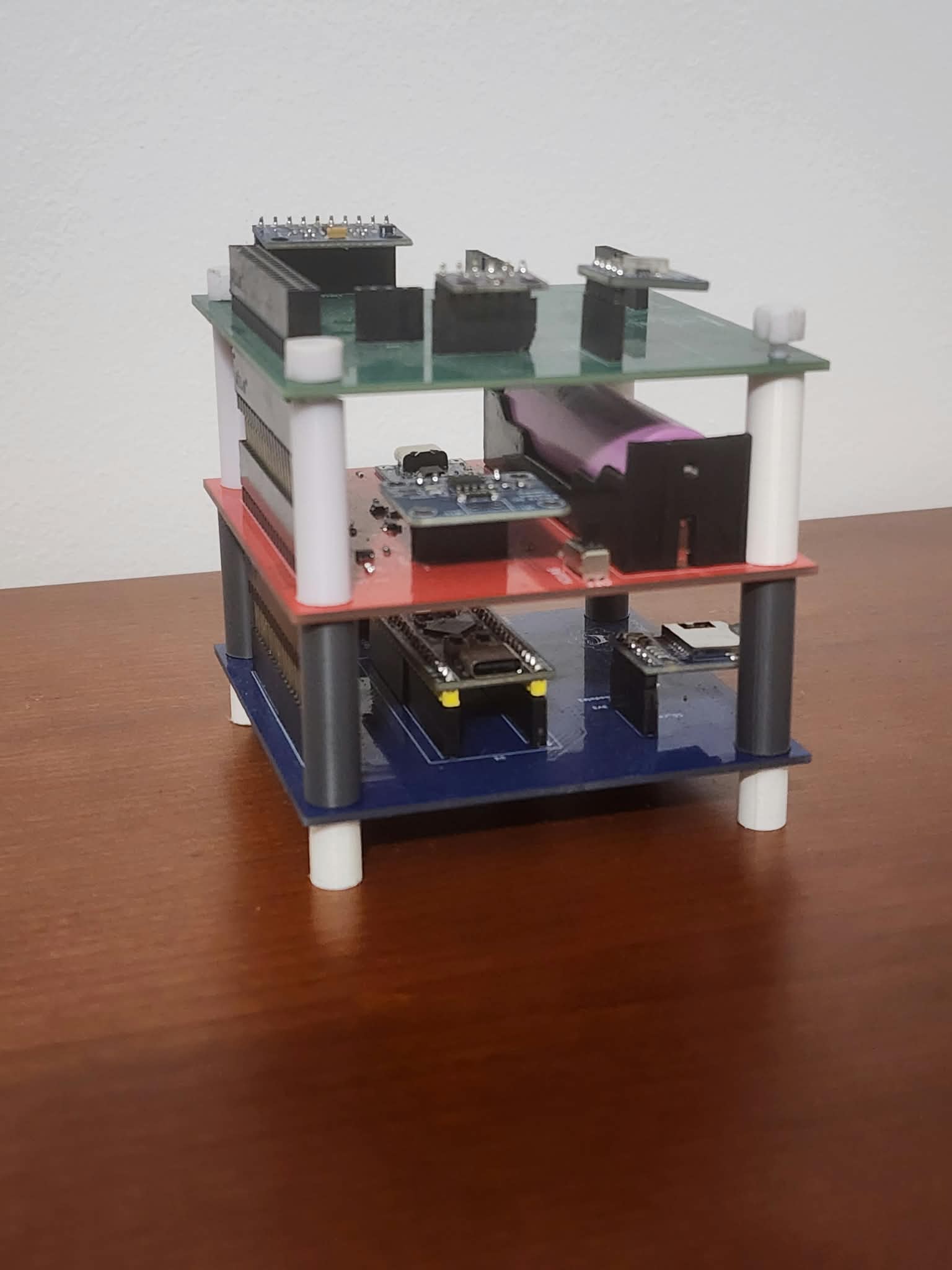
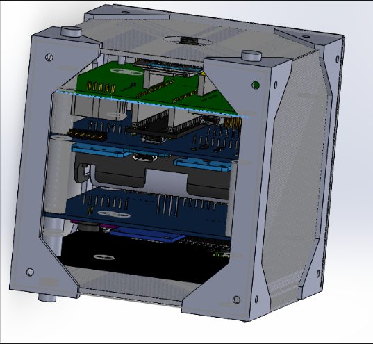
The system is split into three stacked boards connected through a common 40-pin interface. The OBC is the central controller: it acquires sensor data, manages power states, stores telemetry/images, controls the camera and handles the mission logic. The Payload provides the main sensors, GNSS and LoRa radio; the EPS distributes and monitors power.
flowchart LR
    EPS[EPS\nBattery · regulation\nINA219 · switched rails] <--> OBC[OBC\nSTM32F411\nMission logic · storage]
    OBC <--> PAYLOAD[Payload\nMPU6500 · BMP280 · VEML7700\nNEO-7M GNSS · SX1278 LoRa]
    OBC <--> CAM[ESP32-CAM\nImage capture]
    OBC --> SD[microSD\nFATFS · telemetry · images]
    PAYLOAD <--> GS[Ground Station\nLoRa TT&C]
    GS --> PC[Mission Analysis\nPython dashboard · Excel export]
The complete data chain implemented in the prototype is:
Sensors / GNSS / EPS telemetry
            ↓
      STM32F411 OBC
      ↙            ↘
 microSD/FATFS     LoRa TT&C
      ↓                ↓
 stored data       Ground Station
                       ↓
Python analysisThe avionics stack uses three matching approximately 85 × 85 mm, 2-layer PCBs. I designed the schematics and PCB layouts in KiCad and defined the electrical interface between the three boards.
The OBC is based on an STM32F411CEU6 BlackPill and acts as the processing and data-handling board. It connects the STM32 to the other two PCBs and integrates microSD, the ESP32-CAM interface, debugging/programming access and all inter-board buses/control signals.
| OBC PCB layout | OBC schematic |
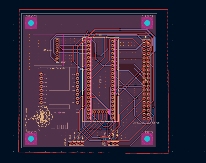 | 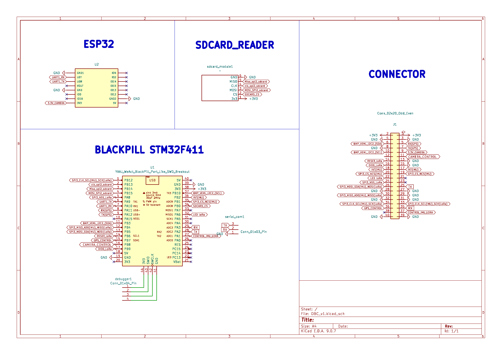 |
KiCad project and schematic PDF →
The EPS provides the battery/charging path, 3.3 V regulation, INA219 housekeeping measurements and independently controlled supply domains for the main avionics loads. Test points and bypass provisions were included to support bring-up and fault isolation.
| EPS PCB layout | EPS schematic |
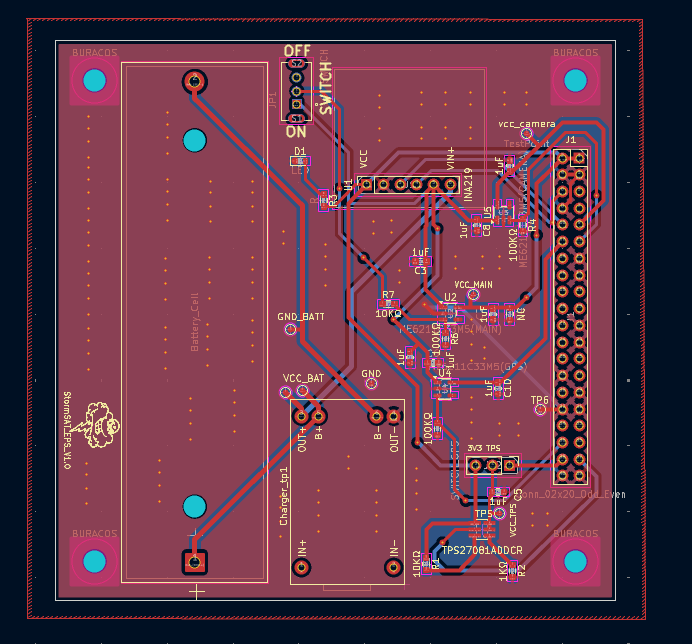 | 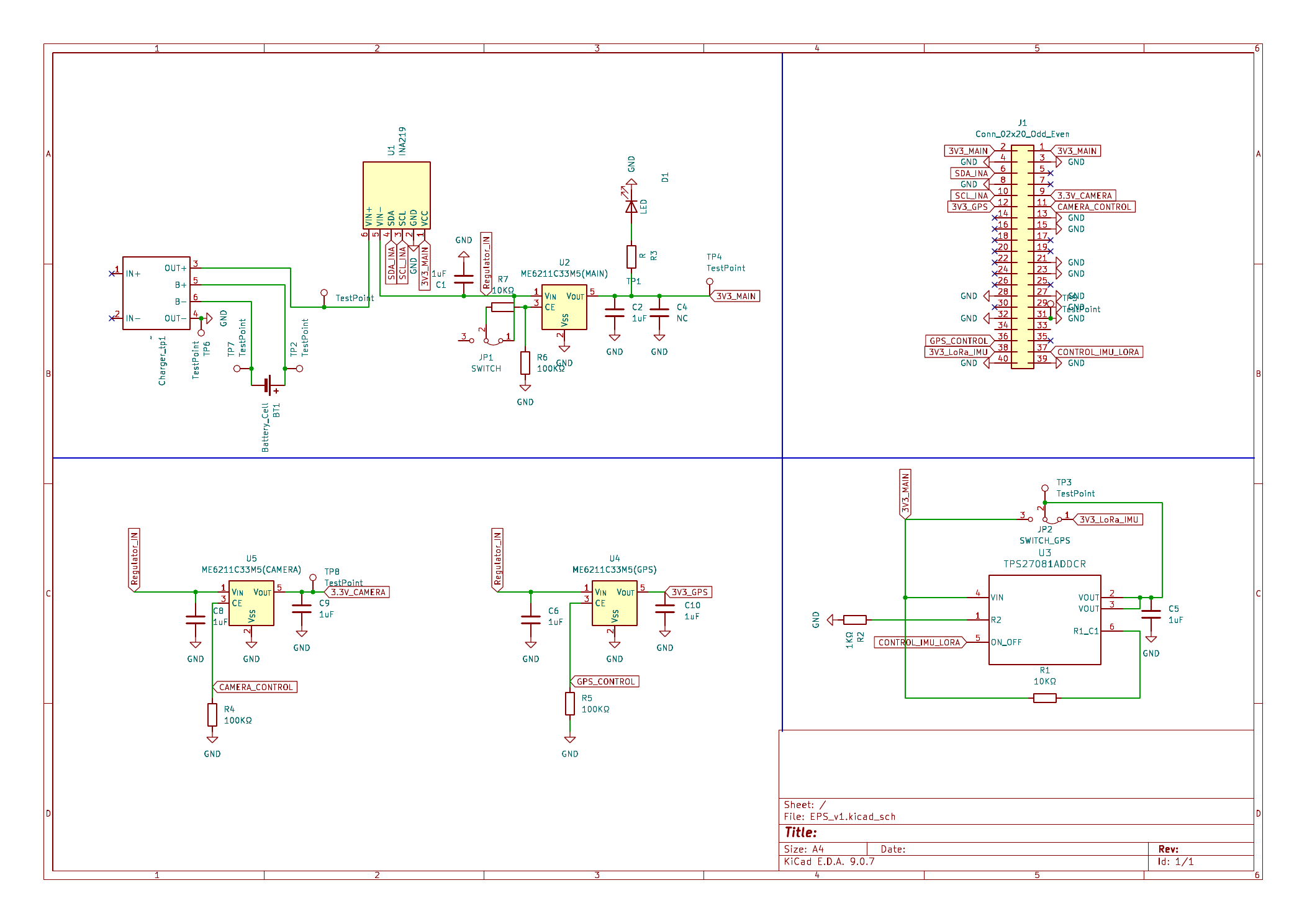 |
KiCad project and schematic PDF →
The Payload PCB contains the main sensing, navigation and TT&C devices: MPU6500, BMP280, VEML7700, u-blox NEO-7M and SX1278/Ra-02.
| Payload PCB layout | Payload schematic |
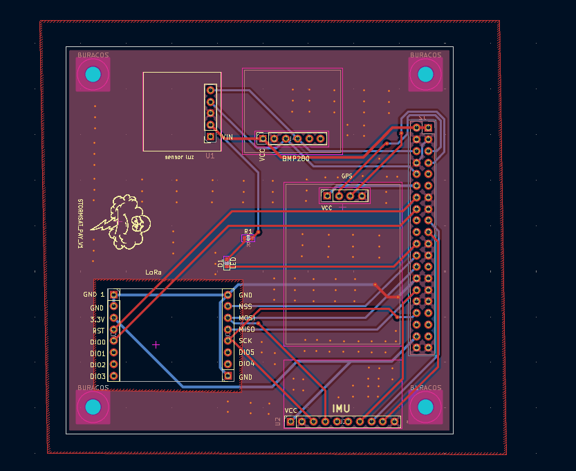 | 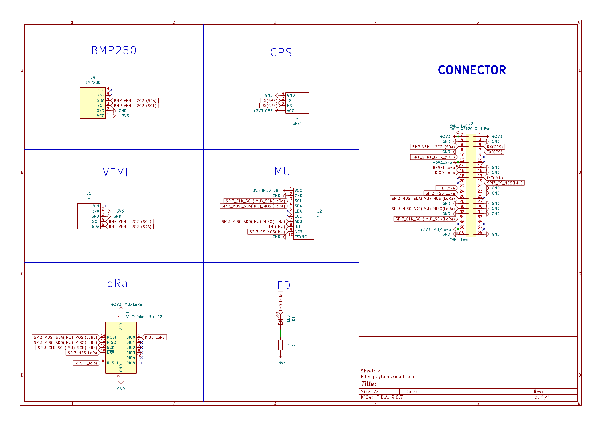 |
KiCad project and schematic PDF →
The final firmware/hardware mapping is:
| Interface | STM32 pins / configuration | Connected hardware |
|---|---|---|
| I²C2 | PB10 SCL, PB3 SDA · 400 kHz | BMP280, VEML7700, INA219 |
| SPI2 | PB13 SCK, PB14 MISO, PB15 MOSI · PB0 CS | microSD |
| SPI3 | PB12 SCK, PB4 MISO, PB5 MOSI | shared by MPU6500 and SX1278 |
| MPU6500 control | PB1 CS, PB2 INT | IMU |
| SX1278 control | PA8 CS, PB6 RESET, PB9 DIO0 | LoRa radio |
| USART1 | PA9 TX, PA10 RX · 921600 baud | ESP32-CAM |
| USART6 | PA11 TX, PA12 RX · 9600 baud | NEO-7M GNSS |
| USART2 | PA2 TX, PA3 RX · 115200 baud | serial debug terminal |
| SWD | PA13 SWDIO, PA14 SWCLK | programming/debugging |
| Power control GPIO | PB7 GPS, PB8 camera | EPS-controlled domains |
The MPU6500 and SX1278 share the SPI3 data/clock lines and are selected independently using dedicated chip-select/control signals. The BMP280, VEML7700 and INA219 share I²C2 using their individual addresses.
More hardware/interface detail →
The final firmware targets the STM32F411CEU6 at 100 MHz and uses STM32 HAL/CMSIS and FATFS.
Despite the task_* filenames, this version does not use FreeRTOS. It uses a cooperative superloop/state-machine architecture. main.c manages the satellite/mission state, and each subsystem module exposes operations such as Init, Run, Sleep, Wake and data access.
At boot the STM32 configures GPIO, ADC, timers, I²C2, SPI2, SPI3, FATFS and the three UARTs. After that, the main loop continuously executes three layers of logic:
1. Mission decision logic
   ├─ read latest sensor / GNSS / EPS data
   ├─ evaluate battery state
   ├─ evaluate geographic mission zones
   └─ select IDLE / SCIENCE / DOWNLINK

2. System configuration
   ├─ enable/disable GPS and camera power
   ├─ put sensors/radio in sleep or wake them
   ├─ trigger telemetry logging
   └─ trigger image capture / pending downlink

3. Cooperative task manager
   ├─ TaskMPU_Run()
   ├─ TaskBMP_Run()
   ├─ TaskVEML_Run()
   ├─ TaskINA_Run()
   ├─ TaskGPS_Run()
   ├─ TaskLoRa_Run()
   ├─ TaskSD_Run()
   └─ camera handling
Timing is mainly based on HAL_GetTick(), so individual modules execute at different rates without requiring an RTOS scheduler.
The firmware supports three top-level satellite modes:
Automatic mission operation uses three mission states:
stateDiagram-v2
    [*] --> IDLE
    IDLE --> SCIENCE: GNSS enters science zone
    SCIENCE --> DOWNLINK: GNSS enters ground-station zone
    SCIENCE --> IDLE: leaves science zone
    DOWNLINK --> SCIENCE: enters science zone
    DOWNLINK --> IDLE: leaves operational zone
IDLE minimises active loads. The environmental sensors, IMU, LoRa, camera and SD can be placed inactive while the GNSS is periodically enabled to determine the current mission zone.
SCIENCE enables the sensing/data-acquisition path. The OBC logs telemetry and evaluates the measured attitude and light level. An image capture can be triggered when roll, pitch and illumination satisfy the configured mission thresholds. If the INA219 indicates a critical battery level, the firmware reduces active loads.
DOWNLINK keeps the LoRa, GNSS and SD path available while non-essential sensing/camera loads are disabled. If a captured image is pending, the file is queued for LoRa transfer.
| Module | Main function in the final firmware | Execution behaviour |
|---|---|---|
task_mpu6500 | SPI IMU acquisition, accel/gyro calibration, roll/pitch estimation | sampled every ~20 ms (50 Hz); complementary filter |
task_bmp280 | temperature/pressure acquisition and sensor sleep/wake | ~5 s measurement period |
task_veml7700 | ambient-light acquisition, configurable gain/integration | ~1 s period |
task_ina219 | bus/shunt voltage, current and power housekeeping | ~1 s period |
task_gps | UART receive, FIFO processing, NMEA filtering/parsing | UART interrupt reception; parser advanced ~every 50 ms |
task_sdcard | FATFS mount/unmount, file operations and telemetry/image storage | storage service used by logging/camera/TT&C |
task_esp32cam | camera command protocol and segmented UART image reception | command/ACK + block reception to SD |
task_lora | TT&C state machine, commands, telemetry and image downlink | TX → RX window → command/timeout handling |
The MPU6500 code calibrates accelerometer/gyroscope offsets and combines accelerometer-derived angles with integrated gyro rates using a complementary filter (alpha = 0.95) to generate roll and pitch estimates used by the mission logic.
Firmware source → · Detailed firmware architecture →
The NEO-7M is connected to USART6. Data is received asynchronously into a FIFO and then processed by the GPS task. Development progressed from raw NMEA output to an application-specific stream:
NEO-7M @ 9600 baud
       ↓
UART interrupt reception
       ↓
FIFO / buffering
       ↓
NMEA filtering + checksum/parsing
       ↓
RMC / GGA fields
       ↓
latitude · longitude · altitude · fix · satellites · UTC
       ↓
mission logic + logging + telemetry
Unnecessary NMEA messages can be disabled and the receiver update period is configurable. The mission logic uses the decoded coordinates to determine when the prototype is in a configured science zone or ground-station/downlink zone.
The Payload uses an SX1278/Ra-02 radio on SPI3. The final configuration in firmware is 433 MHz, 17 dBm, SF7, 500 kHz bandwidth, coding rate 4/5, CRC enabled and preamble length 10.
The application-level TTC packet is:
[ dst ][ src ][ type ][ seq ][ len ][ payload ... ]Implemented packet types include:
DATA       telemetry / stored data
ACK        data acknowledgement
CMD        ground command
ACK_CMD    command acknowledgement
IMG_START  image-transfer metadata
IMG_BLOCK  image data
IMG_ACK    received-block bitmap
IMG_END    transfer completion
The command handler supports operations including GPS/camera enable, satellite-mode changes, telemetry-period configuration, system reset and camera capture/resolution/quality/brightness control.
The link is half-duplex. TaskLoRa_Run() moves through a state machine:
IDLE
  ↓ period elapsed
TX telemetry/data
  ↓
RX WINDOW (~2 s)
  ├─ valid command → execute + ACK_CMD
  ├─ received packet → process
  └─ timeout → return to IDLE
Source/destination IDs and sequence numbers are used to associate packets and acknowledgements instead of treating any received response as valid.
Image handling is a complete multi-device data path rather than a single UART command:
ESP32-CAM
   ↓  USART1 @ 921600
capture metadata + image blocks
   ↓
STM32 OBC
   ↓
FATFS / microSD
   ↓  when downlink is available
read image file
   ↓
150-byte LoRa image blocks
   ↓
windowed ACK bitmap / retransmit missing blocks
   ↓
Ground Station
The LoRa image-transfer implementation uses 150-byte data blocks, windows of up to 32 blocks, timeout/retry handling and retransmission of missing blocks.
| Device | What the OBC uses it for | Interface |
|---|---|---|
| MPU6500 | acceleration, angular rate, roll/pitch estimate and attitude condition for image capture | SPI3 + INT |
| BMP280 | temperature and pressure telemetry | I²C2 |
| VEML7700 | illumination measurement and science/camera condition | I²C2 |
| INA219 | EPS bus voltage, current and power; battery/health decision input | I²C2 |
| NEO-7M | position, fix state, satellites and UTC; mission-zone decisions | USART6 |
| SX1278 | telemetry, telecommand and image downlink | SPI3 + GPIO |
| ESP32-CAM | image acquisition | USART1 + power control |
| microSD | telemetry history and captured image storage | SPI2 + FATFS |
The project was brought up incrementally from individual devices to the complete integrated stack.
| Area | Tests performed |
|---|---|
| LoRa TT&C | PING/PONG, structured DATA packets, src/dst, sequence handling, ACKs, command reception and ACK_CMD |
| GNSS | direct NEO-7M testing, 3D fix, NMEA reception/filtering/parsing and update-rate changes |
| microSD | FATFS mount, file read/write, sensor logging and PC readback |
| INA219 | rail voltage/current/power measurements with different connected loads |
| VEML7700 | gain/integration-time changes, saturation and dynamic-range tests |
| MPU6500 | sensor bring-up, calibration, acquisition and roll/pitch processing |
| Camera | STM32 ↔ ESP32-CAM commands, capture, block reception and SD storage |
| Integrated chain | onboard acquisition → storage/TT&C → ground reception → Python analysis/export |
Recorded examples included a GNSS 3D fix with HDOP ≈ 1.6, FATFS sensor logging, and INA219 measurements used to compare the contribution of the connected payload loads.
Detailed validation and known issues →
I independently developed the Python application used to visualise and analyse mission telemetry.
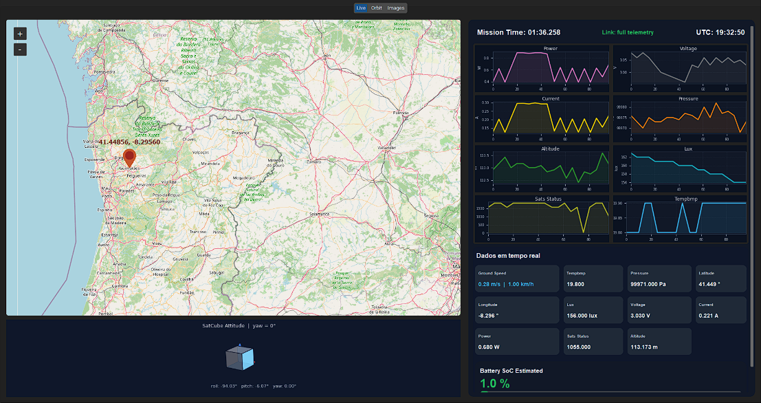
It processes live/recorded telemetry and provides position/map visualisation, attitude and sensor plots, battery/mission information, summaries and Excel export.
Mission-analysis source → · Example export →
A separate image-analysis application is preserved in software/image-analysis/ because it formed part of the team workflow; it was developed by another team member and is not presented as my work.
My main work on StormSat was:
Detailed contribution record →
During final EPS bring-up, the TPS27081A switched IMU/LoRa power path presented a short-circuit condition. The board included a bypass provision, so the affected switched path was isolated and bypassed to continue validating the rest of the system.
I keep this documented because fault isolation and continuing the integration campaign were part of the actual engineering work.
StormSat-CubeSat/
├── hardware/              KiCad projects, schematics, PCB layouts and Gerbers
├── firmware/              complete STM32F411 CubeIDE project
├── software/              mission-analysis + team image-analysis applications
├── examples/              sample mission export
├── docs/
│   ├── engineering.md     deeper hardware/firmware/system description
│   ├── verification.md    tests, measurements and known issue
│   ├── my-contributions.md
│   └── assets/
├── NOTICE.md
└── THIRD_PARTY.mdStormSat is an engineering prototype, not flight-qualified hardware. I do not claim ECSS qualification, radiation tolerance, thermal-vacuum/vibration qualification or formal EMC/EMI compliance.
The objective of this revision was to take a complete embedded avionics system through requirements interpretation, schematic/PCB design, manufacture, firmware integration, bring-up, debugging and end-to-end functional validation.
| Qty | Value | Footprint | References |
|---|---|---|---|
| 4 | MountingHole_3.2mm_M3 | MountingHole:MountingHole_3.2mm_M3 | BURACOS, BURACOS, BURACOS, BURACOS |
| 1 | BMP280 | sensores:BMP | U4 |
| 1 | Conn_02x20_Odd_Even | Connector_PinHeader_2.54mm:PinHeader_2x20_P2.54mm_Vertical | J2 |
| 1 | LED | LED_SMD:LED_0603_1608Metric | D1 |
| 1 | LOGO | LOGO | G*** |
| 1 | LoRa | sensores:LoRa | U3 |
| 1 | R | Resistor_SMD:R_0603_1608Metric | R1 |
| 1 | ~ | sensores:VEML7700 | U1 |
| 1 | ~ | sensores:gps | GPS1 |
| 1 | ~ | sensores:IMU | U2 |
It measures 85 × 85 mm and has 2 copper layers, 1.6 mm thick.
13 parts, built around the BMP280. The full list of its parts is on this page, with links to each part's symbol and footprint where PCBKit's library has them.
From the Migsster/StormSat-CubeSat repository on GitHub, at the commit this page was made from: the board is hardware/Payload/payload.kicad_pcb and its schematic hardware/EPS/EPS_v1.kicad_sch. PCBKit opens the board in the browser, with nothing to install.
Its repository states no licence, so its author keeps all rights: ask Migsster before reusing the design.
Migsster/StormSat-CubeSat
1U CubeSat avionics prototype with custom OBC/EPS/Payload PCBs, STM32 embedded firmware, LoRa TT&C, GNSS and Python mission analysis.

Migsster/StormSat-CubeSat
1U CubeSat avionics prototype with custom OBC/EPS/Payload PCBs, STM32 embedded firmware, LoRa TT&C, GNSS and Python mission analysis.

pms67/LittleBrain-STM32F4-Sensorboard
STM32F4-based PCB interfacing with a variety of sensors.

aeonSolutions/AeonLabs-AI-Volvo-MKII-Open-Hardware
Volvo MKII Open Hardware


phonght32/OpenDrone_HW_AIO_FC_F405
OpenDrone Project - AIO Brushless FC F405.

TheNoobInventor/pi-pico-drone
A micro drone is made using the Raspberry Pi Pico W. It is fitted with the MPU6050 IMU module and BMP280 barometric sensor. The drone will be controlled using TinyMPC and employ a Micro-ROS client on FreeRTOS.


