2 layers25.4 × 57.2 mm
OpenTherm Click
michpro/mikroBUS
Collection of add-on boards in mikroBUS™ standard
58 parts5CERN-OHL-P-2.0
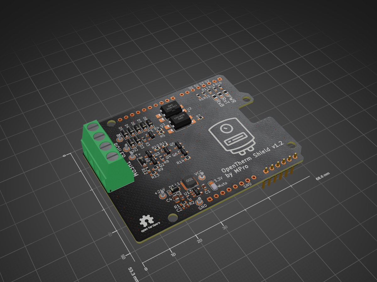
 michpro/Arduino_OpenTherm_shield1
Arduino hardware shield to send and receive data from OpenTherm devices
Arduino OpenTherm shield is an open-source printed circuit board by michpro, from the michpro/Arduino_OpenTherm_shield repository on GitHub, published under the CERN-OHL-P-2.0 licence. It is a 2-layer board of 68.6 × 53.3 mm with 55 parts on 55 nets, routed with 226 tracks and 86 vias.
It is built around the MT3540-F23, LTV-817S and 1N4148W, with the MMBT2907A, MMBT2222A and 1N5819W among its other parts. Its parts include 18 resistors, 12 diodes, 6 transistors, 4 capacitors and 3 ICs. It belongs with the microcontroller boards boards of this library.


The Arduino OpenTherm Shield is an open-source hardware interface designed to enable an Arduino microcontroller to communicate with heating systems using the OpenTherm protocol. OpenTherm is a point-to-point communication protocol commonly used in modern heating systems for efficient control and monitoring. This shield provides the necessary voltage conversion, electrical isolation, and signal conditioning to interface the Arduinos 5V or 3.3V logic with the OpenTherm bus, which typically operates at higher voltages (24V).
This work is based on otgw.tclcode.com project.
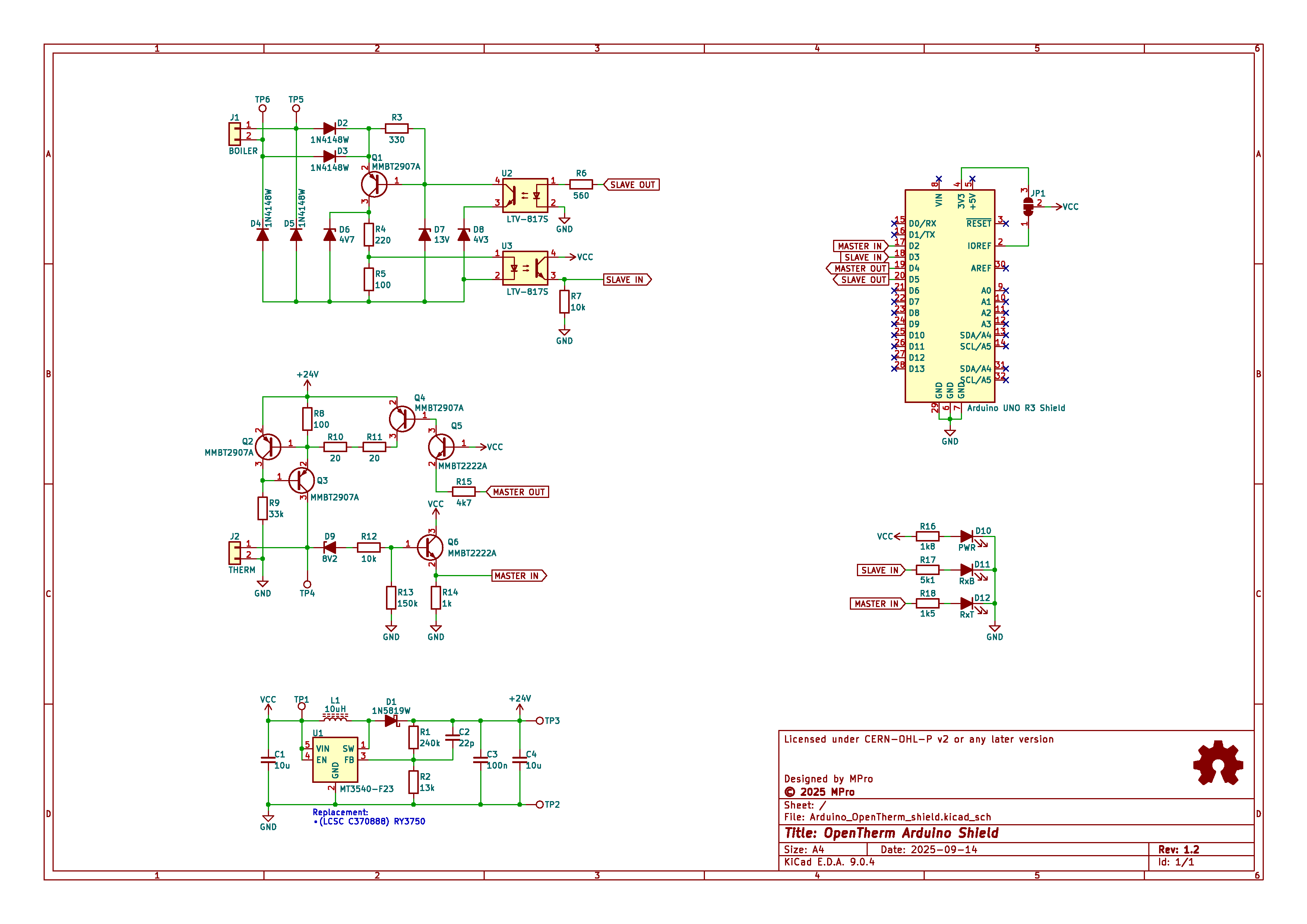
(click on the image to see the 3D model)
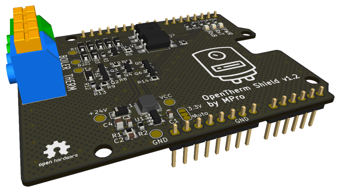
For Arduino UNO:
For WeMos D1 UNO:
Other boards:
Production files can be found here.
Below are the start-up instructions for the "shield_test.ino" Arduino program, a diagnostic tool designed to test and validate the electrical and communication integrity between a boiler and thermostat circuits on the OpenTherm shield. These instructions guide you through the process step-by-step, ensuring you can verify your hardware setup correctly.
Upload the Program
Open Serial Monitor
Initial Setup
y and press Enter to proceed.Voltage Measurement 1
y in the serial monitor to proceed.Voltage Measurement 2
y to proceed.Current Measurement 1
y to proceed.Activate MASTER-OUT and Current Measurement 2
y to proceed.Connect Terminals and Voltage Measurement 3
y to proceed.Check RxB LED
y to proceed.Activate SLAVE-OUT and Voltage Measurement 4
y to proceed.Test Result
*****************
*  TEST PASSED  *
**********************************
* TEST FAIL !!! *
*****************Continuous Testing (if passed)
Follow these instructions carefully to test and validate your OpenTherm shield setup. Each step requires confirmation via the serial monitor, so keep it open and active throughout the process. Successful completion ensures your boiler and thermostat circuits are functioning correctly.
Copyright © 2025 Michal Protasowicki
Hardware part of this project is released under CERN Open Hardware Licence Version 2 - Permissive.

Software part of this project is released under MIT Licence.

If You find my projects interesting and You wanted to support my work, You can give me a cup of coffee or a keg of beer :)
| Qty | Value | Footprint | References |
|---|---|---|---|
| 4 | 1N4148W | footprints:D_SOD-123 | D2, D3, D4, D5 |
| 4 | MMBT2907A | footprints:SOT-23 | Q1, Q2, Q3, Q4 |
| 2 | 100 | footprints:R_0603_1608Metric | R5, R8 |
| 2 | 10k | footprints:R_0603_1608Metric | R7, R12 |
| 2 | 20 | footprints:R_0603_1608Metric | R10, R11 |
| 2 | LTV-817S | footprints:SMDIP-4_W9.53mm | U2, U3 |
| 2 | MMBT2222A | footprints:SOT-23 | Q5, Q6 |
| 1 | +24V | footprints:TestPoint_Pad_D2.0mm | TP3 |
| 1 | 100n | footprints:C_0603_1608Metric | C3 |
| 1 | 10u | footprints:C_0805_2012Metric | C4 |
| 1 | 10u | footprints:C_0603_1608Metric | C1 |
| 1 | 10uH | footprints:Inductor_4.2x4.4mm | L1 |
| 1 | 13V | footprints:D_SOD-123 | D7 |
| 1 | 13k | footprints:R_0603_1608Metric | R2 |
| 1 | 150k | footprints:R_0603_1608Metric | R13 |
| 1 | 1N5819W | footprints:D_SOD-123 | D1 |
| 1 | 1k | footprints:R_0603_1608Metric | R14 |
| 1 | 1k5 | footprints:R_0603_1608Metric | R18 |
| 1 | 1k8 | footprints:R_0603_1608Metric | R16 |
| 1 | 220 | footprints:R_0603_1608Metric | R4 |
| 1 | 22p | footprints:C_0603_1608Metric | C2 |
| 1 | 240k | footprints:R_0603_1608Metric | R1 |
| 1 | 330 | footprints:R_0603_1608Metric | R3 |
| 1 | 33k | footprints:R_0603_1608Metric | R9 |
| 1 | 4V3 | footprints:D_SOD-123 | D8 |
| 1 | 4V7 | footprints:D_SOD-123 | D6 |
| 1 | 4k7 | footprints:R_0603_1608Metric | R15 |
| 1 | 560 | footprints:R_0603_1608Metric | R6 |
| 1 | 5k1 | footprints:R_0603_1608Metric | R17 |
| 1 | 8V2 | footprints:D_SOD-123 | D9 |
| 1 | Arduino UNO R3 Shield | footprints:Arduino_UNO_R3_WithMountingHoles_Profiled | A1 |
| 1 | B1 | footprints:TestPoint_Pad_D2.0mm | TP5 |
| 1 | B2 | footprints:TestPoint_Pad_D2.0mm | TP6 |
| 1 | BOILER | footprints:Altech_AK100_1x02_P5.00mm | J1 |
| 1 | GND | footprints:TestPoint_Pad_D2.0mm | TP2 |
| 1 | Logo_Open_Hardware_Small | footprints:OSHW-Logo2_7.3x6mm_SilkScreen | LOGO3 |
| 1 | MT3540-F23 | footprints:SOT-23-5 | U1 |
| 1 | PWR | footprints:LED_0805_2012Metric | D10 |
| 1 | RxB | footprints:LED_0805_2012Metric | D11 |
| 1 | RxT | footprints:LED_0805_2012Metric | D12 |
| 1 | T+ | footprints:TestPoint_Pad_D2.0mm | TP4 |
| 1 | THERM | footprints:Altech_AK100_1x02_P5.00mm | J2 |
| 1 | VCC | footprints:TestPoint_Pad_D2.0mm | TP1 |
| 1 | VCC | footprints:SolderJumper-3_P1.3mm_Bridged12_RoundedPad1.0x1.5mm | JP1 |
michpro/mikroBUS
Collection of add-on boards in mikroBUS™ standard

anway0404/Arduino_OpenTherm_shield
Arduino hardware shield to send and receive data from Opentherm devices

butchja/esphome-jk-bms-can-PCB
HW platform for https://github.com/Ackmaniac/esphome-jk-bms-can

cnlohr/cnhardware
My dumping grounds for all my kicad projects and random hardware bringup.

Marcus10110/DelSolClock
This is a project to replace the clock in my car with an ESP32 and a small display.


Nec0ti/KISRAK-M1
A high-performance, logic-level H-Bridge motor driver. Features discrete MOSFET design with passive hardware dead-time protection and 3.3V logic compatibility.

mirdej/synkie
The Synkie is a modular open source analog video processor, developed by Michael Egger, Max Egger and Flo Kaufmann
It measures 68.6 × 53.3 mm and has 2 copper layers, 1 mm thick.
55 parts, built around the MT3540-F23, LTV-817S, 1N4148W and MMBT2907A. The full list of its parts is on this page, with links to each part's symbol and footprint where PCBKit's library has them.
From the michpro/Arduino_OpenTherm_shield repository on GitHub, at the commit this page was made from: the board is Arduino_OpenTherm_shield.kicad_pcb and its schematic Arduino_OpenTherm_shield.kicad_sch. PCBKit opens the board in the browser, with nothing to install.
Its repository publishes it under the CERN-OHL-P-2.0 licence: you may reuse it on that licence's terms (keep the author's notice, and for a copyleft licence share your changes alike).