2 layers25.4 × 57.2 mm
OpenTherm Click
michpro/mikroBUS
Collection of add-on boards in mikroBUS™ standard
58 parts5CERN-OHL-P-2.0

 Nec0ti/KISRAK-M11
A high-performance, logic-level H-Bridge motor driver. Features discrete MOSFET design with passive hardware dead-time protection and 3.3V logic compatibility.
KISRAK M1 is an open-source printed circuit board by Nec0ti, from the Nec0ti/KISRAK-M1 repository on GitHub, published under the AGPL-3.0 licence. It is a 2-layer board of 38.5 × 49 mm with 35 parts on 11 nets, routed with 157 tracks and 0 vias.
It is built around the UT2305G-AE3-R, 1N4148WS and MMBT2222A, with the MMBT2907A among its other parts. Its parts include 9 transistors, 6 resistors, 6 diodes, 4 capacitors and 1 connector. It belongs with the robots and motor control and interfaces and adapters boards of this library.


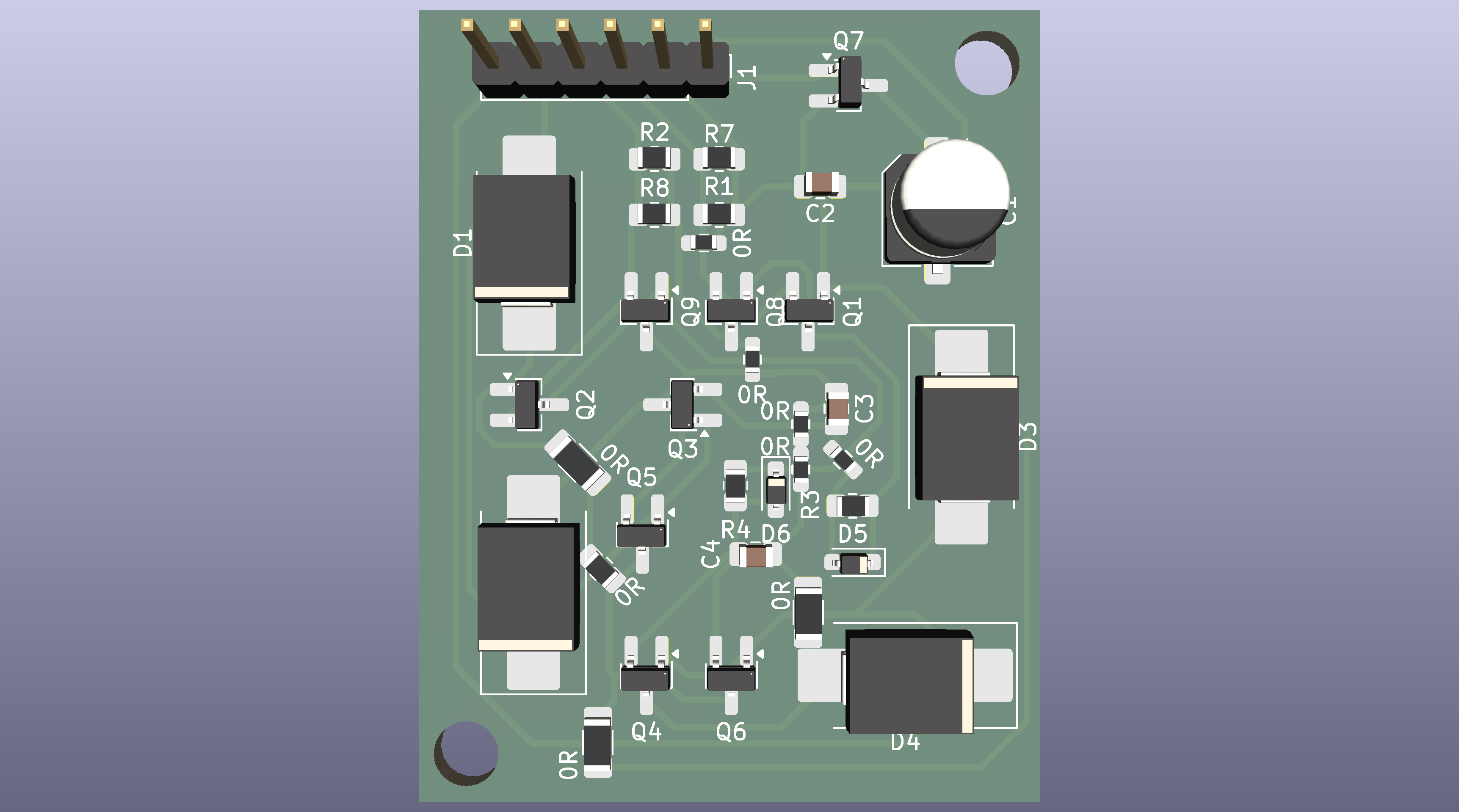
KISRAK-M1 is a high-efficiency, discrete H-Bridge motor driver designed for micro-robotics.
This project uses an RC-D circuit (47R, 2.2nF, 1N4148) to create asymmetrical switching times, preventing shoot-through without complex MCU PWM dead-time configuration.
For in-depth technical details, design philosophy, and fabrication guides, please refer to the official documentation.
To understand the competitive robotics context for which KISRAK-M1 is designed, watch this excellent overview of Micromouse competitions:

| Qty | Value | Footprint | References |
|---|---|---|---|
| 5 | R_0603_1608Metric_Pad0.98x0.95mm_HandSolder | Resistor_SMD:R_0603_1608Metric_Pad0.98x0.95mm_HandSolder | 0R, 0R, 0R, 0R, 0R |
| 4 | SS34-HT | Diode_SMD:D_SMC_Handsoldering | D1, D2, D3, D4 |
| 3 | R_1206_3216Metric_Pad1.30x1.75mm_HandSolder | Resistor_SMD:R_1206_3216Metric_Pad1.30x1.75mm_HandSolder | 0R, 0R, 0R |
| 3 | UT2305G-AE3-R | Package_TO_SOT_SMD:SOT-23_Handsoldering | Q5, Q6, Q7 |
| 2 | 100k | Resistor_SMD:R_0805_2012Metric_Pad1.20x1.40mm_HandSolder | R1, R2 |
| 2 | 10k | Resistor_SMD:R_0805_2012Metric_Pad1.20x1.40mm_HandSolder | R7, R8 |
| 2 | 1N4148WS | Diode_SMD:D_SOD-323_HandSoldering | D5, D6 |
| 2 | 2.2nF | Capacitor_SMD:C_0805_2012Metric_Pad1.18x1.45mm_HandSolder | C3, C4 |
| 2 | 47R | Resistor_SMD:R_0805_2012Metric_Pad1.20x1.40mm_HandSolder | R3, R4 |
| 2 | MMBT2222A | Package_TO_SOT_SMD:SOT-23_Handsoldering | Q1, Q2 |
| 2 | MMBT2907A | Package_TO_SOT_SMD:SOT-23_Handsoldering | Q8, Q9 |
| 2 | UTM2054G-AE3-R | Package_TO_SOT_SMD:SOT-23_Handsoldering | Q3, Q4 |
| 1 | 100nF | Capacitor_SMD:C_0805_2012Metric_Pad1.18x1.45mm_HandSolder | C2 |
| 1 | 100uF | Capacitor_SMD:CP_Elec_6.3x5.2 | C1 |
| 1 | R_0805_2012Metric_Pad1.20x1.40mm_HandSolder | Resistor_SMD:R_0805_2012Metric_Pad1.20x1.40mm_HandSolder | 0R |
| 1 | ~ | Connector_PinHeader_2.54mm:PinHeader_1x06_P2.54mm_Vertical | J1 |
michpro/mikroBUS
Collection of add-on boards in mikroBUS™ standard

anway0404/Arduino_OpenTherm_shield
Arduino hardware shield to send and receive data from Opentherm devices

Marcus10110/DelSolClock
This is a project to replace the clock in my car with an ESP32 and a small display.


michpro/Arduino_OpenTherm_shield
Arduino hardware shield to send and receive data from OpenTherm devices

mirdej/synkie
The Synkie is a modular open source analog video processor, developed by Michael Egger, Max Egger and Flo Kaufmann

promesoft/KicadJE-SteinerVCF
Adoption of the original 1974 steiner VCF THT+SMD - And ICL8083 VCO RevB

henkjannl/RoomThermostat
Opentherm room thermostat that can be controlled through Telegram, but also locally
It measures 38.5 × 49 mm and has 2 copper layers, 1.6 mm thick.
35 parts, built around the UT2305G-AE3-R, 1N4148WS, MMBT2222A and MMBT2907A. The full list of its parts is on this page, with links to each part's symbol and footprint where PCBKit's library has them.
From the Nec0ti/KISRAK-M1 repository on GitHub, at the commit this page was made from: the board is Hardware/kicad_project/kisrak-m1.kicad_pcb and its schematic Hardware/kicad_project/kisrak-m1.kicad_sch. PCBKit opens the board in the browser, with nothing to install.
Its repository publishes it under the AGPL-3.0 licence: you may reuse it on that licence's terms (keep the author's notice, and for a copyleft licence share your changes alike).