Canary is an open-source printed circuit board by michael-michelotti, from the michael-michelotti/canary repository on GitHub. It is a 2-layer board of 65 × 56 mm with 26 parts on 36 nets, routed with 175 tracks and 28 vias.
It is built around the BMP388, SGP40-D-R4 and TMP119AIYBGR, with the CAT24C32WI-GT3 and TPD2E001DZDR among its other parts. Its parts include 8 capacitors, 5 resistors, 5 ICs, 2 diodes and 2 connectors. It belongs with the sensors and measurement boards of this library.
A custom TMP119 driver, forked from the upstream tmp117.c to handle the TMP119 device ID
A device-tree-driven bring-up of the remaining sensors using upstream Linux drivers (sht4x, bmp280)
A self-heating compensation model calibrated using a stress-sweep linear regression and applied in MQTT service
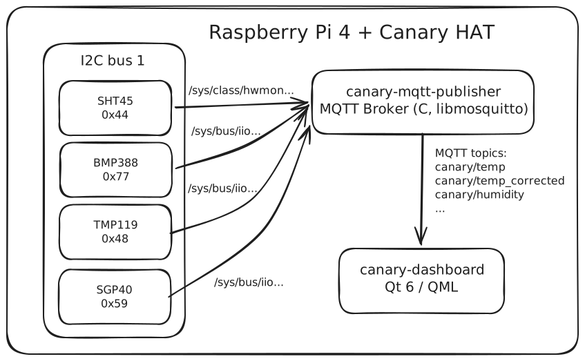
A C publisher daemon that polls sysfs/IIO/hwmon and pushes JSON over MQTT
A Qt 6 / QML dashboard that subscribes to the broker and renders live charts
Sensors and architecture
Sensor
Measures
Bus address
Driver
Sensirion SHT45
Temperature, humidity
0x44
upstream sht4x (hwmon)
Bosch BMP388
Pressure, altitude
0x77
upstream bmp280 (IIO), bosch,bmp380 compatible
TI TMP119
High-accuracy temperature
0x48
custom tmp119.ko (IIO)
Sensirion SGP40
VOC index
0x59
custom sgp40_voc.ko (IIO)
All four sensors share I2C bus 1 (SDA=GPIO2, SCL=GPIO3) with the Pi's on-board 1.8 kΩ pull-ups. On the prototype, breakouts are daisy-chained through a Stemma QT 5-port hub; on the v1 PCB the bare sensors share a single I2C bus.
Each sensor is bound to its driver via a device-tree overlay declaring its compatible string and I2C address. Sources live in overlays/ and are compiled with dtc -@ -I dts -O dtb -o <name>.dtbo <name>.dts.
There are two ways the kernel learns about the board:
Device Tree Overlays: Each .dtbo is copied to /boot/firmware/overlays/ and added to /boot/firmware/config.txt as a dtoverlay= line. The Broadcom bootloader merges the overlays at boot and the kernel binds drivers as it walks the I2C bus.
HAT Configuration: The HAT spec defines an I2C EEPROM at 0x50 on I2C bus 0 that holds a vendor/product ID and an embedded device-tree fragment. When the bootloader detects it, the DT is merged automatically.
Kernel module availability
Driver setup for the four sensors:
Driver
Source
Stock Pi kernel
Action
sht4x
upstream
=m
overlay only
bmp280
upstream
=m
overlay only
tmp119
custom (tmp119/)
n/a
build .ko against raspberrypi-kernel-headers, install to /lib/modules/$(uname -r)/extra/
sgp40_voc
custom (sgp40_voc/)
n/a
build .ko against raspberrypi-kernel-headers, install to /lib/modules/$(uname -r)/extra/; stock sgp40 blacklisted in /etc/modprobe.d/sgp40-blacklist.conf
Self-heating compensation
The Pi 4 SoC heats the temperature sensors by about 4°C even at idle. The correction is a property of board geometry and airflow, so it lives in the publisher daemon, not the sensor kernel drivers themselves.
Model
I utilize the following compensation model, popularized by the Enviro+ project:
t_cpu is read from /sys/class/thermal/thermal_zone0/temp and run through a single-pole EWMA (α = 0.05 at the 2s publish cadence, resulting in a lowpass with a 39s time constant) before entering the formula — raw SoC temperature jitters several degrees between samples and would inject visible noise into the corrected output.
FACTOR is the thermal coupling constant for that sensor's board location; higher means looser coupling. It is calibrated using real measured data, and is a property of the board configuration, housing, and operating environment.
Calibration
Stress-ramp sweep using stress-ng --cpu N, holding 15-20 minutes at idle / 1 core at 50 % / 1c / 2c / 3c / 4c. The mean of the last 5 minutes of each step gives one (t_cpu, t_sensor) point. Linear regression with x = t_cpu − t_sensor, y = t_sensor yields slope 1/FACTOR and intercept corrected t_ambient.
Tools used:
tools/log_temps.py — CSV logger, runs on the Pi during the sweep
Calibrated values for the deployed board (no enclosure, no wind, ~24°C true ambient):
Sensor
FACTOR
Ambient intercept
Notes
TMP119
3.31
24.2°C
within 1°F of cheap reference sensors
SHT45
2.90
—
lower FACTOR = closer to the SoC heat path
Recalibration is required if the HAT goes into an enclosure, gets a heatsink or fan, or otherwise sees a meaningful change in airflow.
Humidity correction
Relative humidity is temperature-dependent, so the SHT45 RH reading must be converted from "RH at the heated sensor surface" to "RH at ambient" using the Magnus equation:
T_sensor comes from the SHT45 hwmon output; T_ambient is the corrected SHT45 temperature from the model above.
What the SGP40 sees
The SGP40's VOC index algorithm needs T/RH at the gas-sensor surface (close to the raw SHT45 measurements, not the corrected ones). The compensation feeder daemon therefore writes raw, uncorrected SHT45 values to the SGP40 via sysfs.
Custom SGP40 driver
An IIO driver assembled by combining two existing pieces: the upstream sgp40.c driver supplies the I2C wire protocol and IIO scaffolding, and Sensirion's reference VOC Index Algorithm (fixed-point implementation) is dropped in alongside it. The interesting work is in connecting these components in kernel context, not in writing the algorithm or the protocol from scratch. Lives in sgp40_voc/ and builds out-of-tree against raspberrypi-kernel-headers.
text
sgp40_voc/
  sgp40_voc_main.c    — driver proper: I2C protocol, IIO channels,
                        read_raw / write_raw, 1 Hz delayed_work, probe
  sgp40_voc_algo.c    — port of Sensirion's VOC Index Algorithm
                        (NOX paths stripped; SGP40 is VOC-only hardware)
  sgp40_voc_algo.h    — Q16.16 fixed-point primitives, algorithm state
  Makefile            — kbuild composite module: sgp40_voc-objs := main.o algo.o
Architectural decisions
I2C wire protocol borrowed from upstream sgp40.c. CRC-8 framing, RH/temperature tick encoding, the measure_raw command sequence.
Q16.16 fixed-point copied from Sensirion's reference. The fix16_t primitives in sgp40_voc_algo.h are taken verbatim from Sensirion's fixpoint reference (BSD-3-Clause, derived from libfixmath). The F16() macro contains a float multiply, but it only runs on compile-time constants, so -O2 folds it to integer constants and the resulting .ko has no floating-point references.
1 Hz delayed_work owns the sample cadence, not userspace. The algorithm's time constants, init durations and blackout window are all time-indexed. cancel_delayed_work_sync is registered via devm_add_action_or_reset to handle teardown cleanly even though the work self-requeues.
read_raw for IIO_CHAN_INFO_PROCESSED returns a cached value under the lock. Userspace can cat the sysfs attribute at any frequency without perturbing the algorithm.
Compensation arrives via sysfs, not via in-kernel sensor coupling. A small systemd-managed bash daemon (userspace/sgp40-compensation/) pipes hwmon → IIO every 10 s, writing to out_temp_raw and out_humidityrelative_raw.
Validation
The ported algorithm was referenced against the existing Sensirion gas-index-algorithm implementation. A sanity check on the running driver confirms the expected behavior: the VOC index ramps up over the first 45 seconds and then settles to a baseline near 100 in clean air.
TMP119 driver
The TMP119 is a newer revision of the TMP117. The upstream tmp117.c driver checks the device ID register and warns about unexpected revision bits, but its fallback path lets the chip initialize and operate correctly.
Instead of relying on that, I wrote a custom driver in tmp119/ which reads the correct portion of the device ID and revision, and correctly binds to the TMP119.
MQTT pipeline and Qt dashboard
End-to-end live data: kernel driver → sysfs → C publisher → MQTT broker → Qt/QML dashboard on a laptop.
Single-file C program linking libmosquitto. Key design points:
Sensor discovery by name attribute. Sysfs numbering (hwmon0, iio:device2, …) is not stable across reboots. The sensor table declares the driver's name string (e.g. sgp40_voc, tmp119); at startup the daemon scans /sys/class/hwmon/ and /sys/bus/iio/devices/ and records the resolved path.
IIO _raw × _scale pattern. TMP119 doesn't expose in_temp_input, only in_temp_raw plus in_temp_scale (milli-°C per LSB). The sensor struct has an optional scale_attr; when present I read both and multiply, then apply a static 0.001 to land in °C.
mosquitto_loop_start(). Background thread handles the protocol and auto-reconnects. Main thread sleeps 2s then publishes.
Topics
One topic per sensor, all with the same payload shape ({"ts":<unix_sec>, "value":<float>, "unit":"<string>"}, QoS 0).
Topic
Source
Unit
canary/temp
TMP119 (IIO)
°C
canary/temp_corrected
TMP119, ambient-corrected
°C
canary/temp_sht45
SHT45 (hwmon)
°C
canary/temp_sht45_corrected
SHT45, ambient-corrected
°C
canary/humidity
SHT45 (hwmon)
%RH
canary/humidity_corrected
SHT45 RH, ambient-corrected
%RH
canary/pressure
BMP388 (IIO)
kPa
canary/voc
SGP40 custom driver (IIO)
VOC index
Raw and corrected topics live side-by-side. Useful for debugging and for visualizing the accuracy of the correction relative to known truth sources.
Qt 6.11 / QML, MinGW 64-bit. Subscribes to canary/# over the LAN.
mqttcontroller.{h,cpp} — QML_ELEMENT-registered QObject owning a QMqttClient, parses JSON, emits (t, value) signals per sensor
SensorChart.qml — reusable card: title, large readout, GraphsView + LineSeries, 300-point ring buffer, 60-second sliding x-axis
Main.qml — ApplicationWindow with a header and a GridLayout of five SensorChart instances.
Uses QtGraphs (the Qt Charts successor)
PCB
The custom PCB KiCad project lives in pcb/ (canary.kicad_pro, canary.kicad_sch, canary.kicad_pcb). The v1 fabrication design is complete, and the board was fabricated by JLCPCB.
40-pin GPIO header pinout matches the Pi HAT spec
AT24C32 EEPROM at I2C address 0x50 on bus 0 for HAT auto-detection
I2C net carries all four sensors; pull-ups intentionally omitted (Pi provides 1.8 kΩ on-board)
Upstream patch: submit "ti,tmp119" compatible entry to tmp117.c.
Auto-reconnect in the dashboard — QMqttClient does not reconnect by default; a small QTimer retry on disconnect is needed before the dashboard survives a Pi reboot.
Historical logging. SQLite alongside the publisher would turn this from a live view into 24-hour trends.
Recalibrate against more reliable truth sources to better validate the compensation model and ambient intercept.
v2 board physically separating the temperature/humidity sensors from the SoC heat path so that compensation error isn't so severe.
Pumper is an experimental RP2354-based USB Audio Class 2 DAC. The board uses a PCM5102A DAC with OPA1652 and OPA1622 analog stages in a compact design intended for learning about USB audio and DAC hardware.
You can find the source KiCad files for the Gliss module in this repository. This project is open hardware and under the Creative Commons Share Alike license 4.0.
A 4-layer embedded development board featuring RP2040, USB2244 high-speed eMMC bridge, dual Type-C ports, and INA226/TMP119 power & telemetry monitoring.
133 partsMIT
Questions
How big is the Canary PCB?
It measures 65 × 56 mm and has 2 copper layers, 1.6 mm thick.
What parts does the Canary use?
26 parts, built around the BMP388, SGP40-D-R4, TMP119AIYBGR and CAT24C32WI-GT3. The full list of its parts is on this page, with links to each part's symbol and footprint where PCBKit's library has them.
Where can I download the Canary KiCad files?
From the michael-michelotti/canary repository on GitHub, at the commit this page was made from: the board is pcb/canary.kicad_pcb and its schematic pcb/canary.kicad_sch. PCBKit opens the board in the browser, with nothing to install.
Can I use the Canary design in my own project?
Its repository states no licence, so its author keeps all rights: ask michael-michelotti before reusing the design.