4 layers100 × 65 mm

 mgsin30/Robocon2025-PCB
高専ロボコン2025のために製作した基板
GPIOBoard is an open-source printed circuit board by mgsin30, from the mgsin30/Robocon2025-PCB repository on GitHub. It is a 2-layer board of 70 × 45 mm with 93 parts on 82 nets, routed with 511 tracks and 104 vias.
It is built around the CH340E, MCP25612FD-E/SL and TLV1117-33DCY. Its parts include 31 resistors, 17 diodes, 12 capacitors, 12 connectors and 5 ICs. It belongs with the STM32 boards of this library.


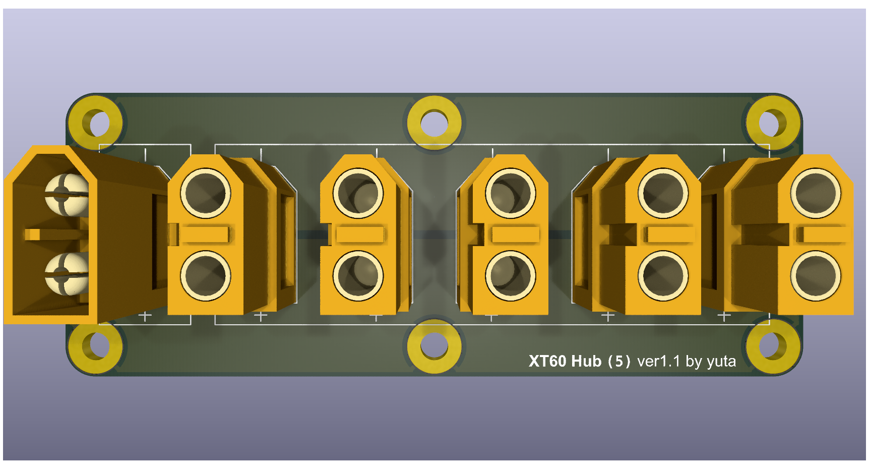
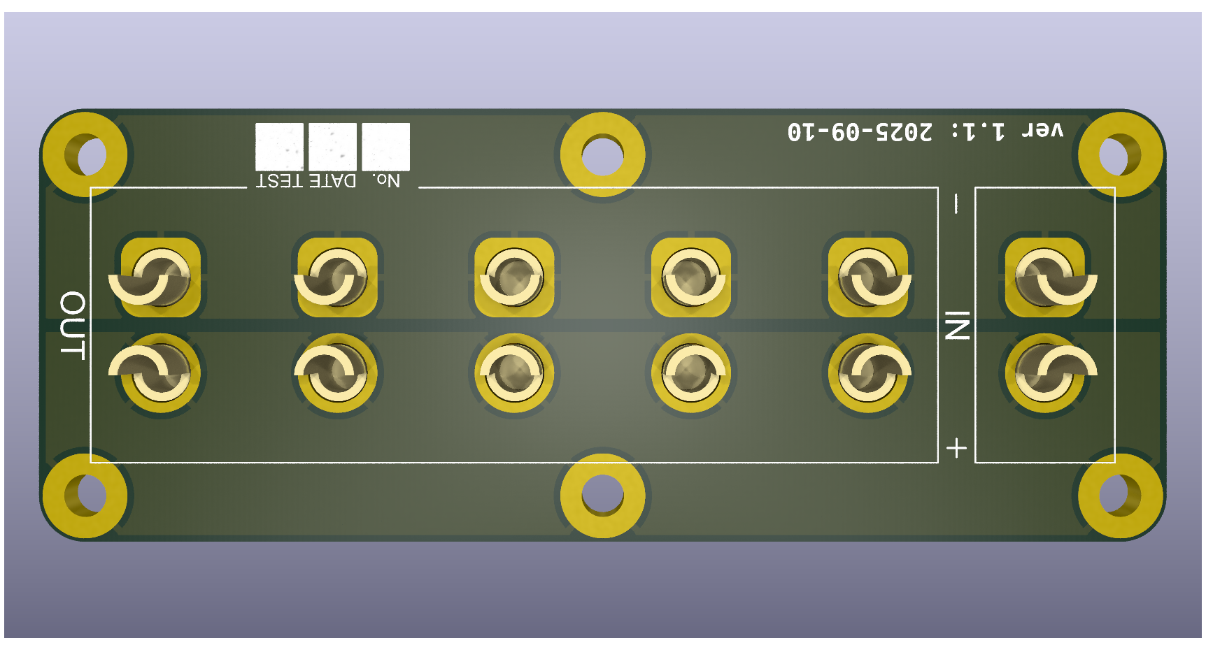
1つの入力を5つの出力に分岐させる XT60 コネクタのハブ
| Qty | Value | Footprint | References |
|---|---|---|---|
| 8 | 330 | Resistor_SMD:R_0603_1608Metric | R9, R10, R11, R12, R13, R14, R15, R16 |
| 8 | 80 | Resistor_SMD:R_0603_1608Metric | R1, R2, R3, R4, R5, R6, R7, R8 |
| 8 | LED | LED_SMD:LED_0603_1608Metric | D1, D2, D3, D4, D5, D6, D7, D8 |
| 6 | 0.1u | Capacitor_SMD:C_0603_1608Metric | C3, C4, C6, C8, C11, C12 |
| 5 | 96 | Resistor_SMD:R_0603_1608Metric | R17, R18, R20, R23, R24 |
| 4 | MountingHole_Pad | MountingHole:MountingHole_3.2mm_M3_Pad | H1, H2, H3, H4 |
| 3 | 4.7u | Capacitor_SMD:C_0603_1608Metric | C1, C2, C5 |
| 2 | 10k | Resistor_SMD:R_0603_1608Metric | R26, R31 |
| 2 | 15p | Capacitor_SMD:C_0603_1608Metric | C9, C10 |
| 2 | 5.1k | Resistor_SMD:R_0603_1608Metric | R21, R22 |
| 2 | D | Diode_SMD:Nexperia_CFP3_SOD-123W | D15, D16 |
| 2 | Polyfuse | Anan-Robo_Footprint_Library:MF-FSMF | F1, F2 |
| 1 | 100 | Resistor_SMD:R_0603_1608Metric | R28 |
| 1 | 120 | Resistor_SMD:R_0603_1608Metric | R25 |
| 1 | 1u | Capacitor_SMD:C_0603_1608Metric | C7 |
| 1 | 300 | Resistor_SMD:R_0603_1608Metric | R30 |
| 1 | 420 | Resistor_SMD:R_0603_1608Metric | R27 |
| 1 | 430 | Resistor_SMD:R_0603_1608Metric | R19 |
| 1 | 600 | Resistor_SMD:R_0603_1608Metric | R29 |
| 1 | CAN | Connector_IDC:IDC-Header_2x03_P2.54mm_Horizontal | J12 |
| 1 | CAN_R | LED_SMD:LED_0603_1608Metric | D17 |
| 1 | CAN_R | Anan-Robo_Footprint_Library:SLW | SW3 |
| 1 | CAN_RX | LED_SMD:LED_0603_1608Metric | D14 |
| 1 | CAN_TX | LED_SMD:LED_0603_1608Metric | D13 |
| 1 | CH340E | Package_SO:MSOP-10_3x3mm_P0.5mm | U3 |
| 1 | Crystal_GND2 | Anan-Robo_Footprint_Library:XRCGB | Y1 |
| 1 | Data | LED_SMD:LED_0603_1608Metric | D12 |
| 1 | Debug | Connector_USB:USB_C_Receptacle_GCT_USB4105-xx-A_16P_TopMnt_Horizontal | J10 |
| 1 | FerriteBead | Inductor_SMD:L_0603_1608Metric | FB1 |
| 1 | GPIO1 | Anan-Robo_Footprint_Library:PAコネクタ(3ピンサイド型) | J1 |
| 1 | GPIO2 | Anan-Robo_Footprint_Library:PAコネクタ(3ピンサイド型) | J2 |
| 1 | GPIO3 | Anan-Robo_Footprint_Library:PAコネクタ(3ピンサイド型) | J3 |
| 1 | GPIO4 | Anan-Robo_Footprint_Library:PAコネクタ(3ピンサイド型) | J4 |
| 1 | GPIO5 | Anan-Robo_Footprint_Library:PAコネクタ(3ピンサイド型) | J5 |
| 1 | GPIO6 | Anan-Robo_Footprint_Library:PAコネクタ(3ピンサイド型) | J6 |
| 1 | GPIO7 | Anan-Robo_Footprint_Library:PAコネクタ(3ピンサイド型) | J7 |
| 1 | GPIO8 | Anan-Robo_Footprint_Library:PAコネクタ(3ピンサイド型) | J8 |
| 1 | IMU | Anan-Robo_Footprint_Library:PAコネクタ(4ピンサイド型) | J9 |
| 1 | LED_GRB | LED_SMD:LED_ROHM_SMLVN6 | U5 |
| 1 | LOGO | Anan-Robo_Footprint_Library:Aho_old_M | G*** |
| 1 | LOGO | Anan-Robo_Footprint_Library:Aho_new_M | G*** |
| 1 | MCP2561/2FD | Package_SO:SOIC-8_3.9x4.9mm_P1.27mm | U4 |
| 1 | MCP2561/2FD selector | Jumper:SolderJumper-2_P1.3mm_Open_Pad1.0x1.5mm | JP1 |
| 1 | PWR | LED_SMD:LED_0603_1608Metric | D11 |
| 1 | RESET | Anan-Robo_Footprint_Library:TVAF06-A020B-R | SW1 |
| 1 | RX | LED_SMD:LED_0603_1608Metric | D10 |
| 1 | STM32F303K8Tx | Package_QFP:LQFP-32_7x7mm_P0.8mm | U1 |
| 1 | SWD | Connector_JST:JST_SH_SM04B-SRSS-TB_1x04-1MP_P1.00mm_Horizontal | J11 |
| 1 | SW_Coded | Anan-Robo_Footprint_Library:RDS-1055-SMT | SW2 |
| 1 | TLV1117-33 | Package_TO_SOT_SMD:SOT-223-3_TabPin2 | U2 |
| 1 | TX | LED_SMD:LED_0603_1608Metric | D9 |
The 91 most common of 93 parts.


It measures 70 × 45 mm and has 2 copper layers, 1.6 mm thick.
93 parts, built around the CH340E, MCP25612FD-E/SL and TLV1117-33DCY. The full list of its parts is on this page, with links to each part's symbol and footprint where PCBKit's library has them.
From the mgsin30/Robocon2025-PCB repository on GitHub, at the commit this page was made from: the board is GPIOBoard/GPIOBoard.kicad_pcb and its schematic CANBusHub/CANBusHub.kicad_sch. PCBKit opens the board in the browser, with nothing to install.
Its repository states no licence, so its author keeps all rights: ask mgsin30 before reusing the design.