

2 layers100 × 100 mm

 mfhepp/gobox-power14
A 6-9-12V DC-DC boost converter for QRP rigs from 4 NiMH cells (or 2S LiPo with minor mods), e.g. Mountain Topper MTR-3B and MTR-5B.
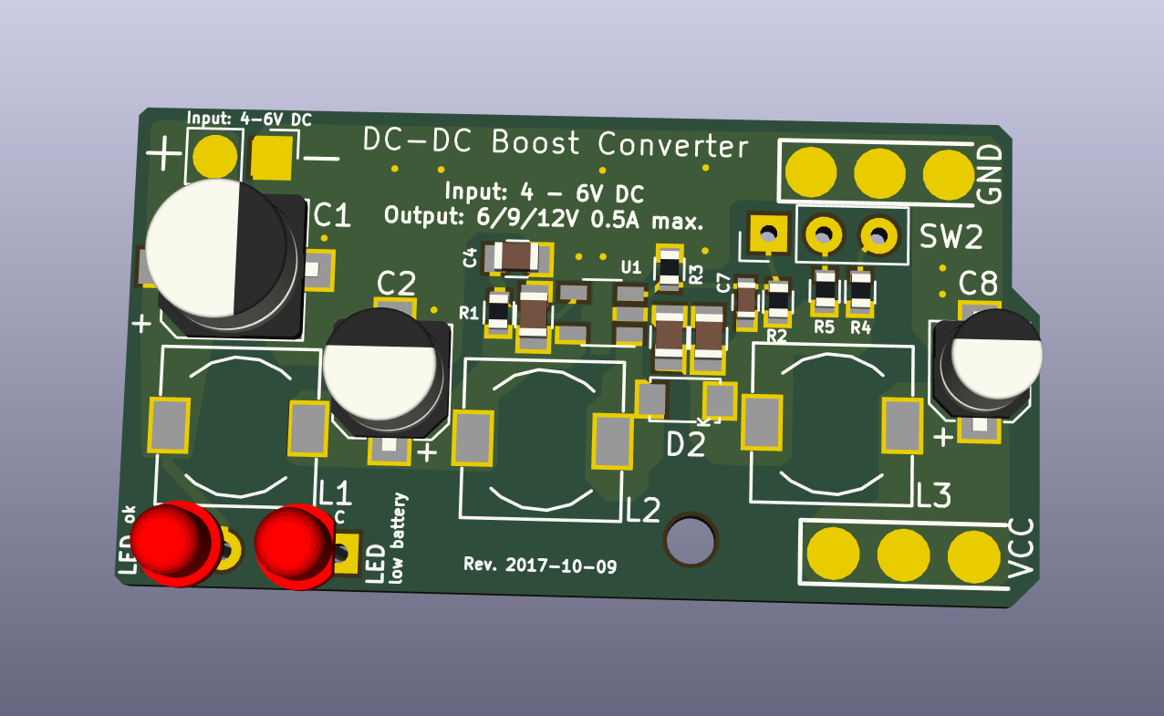
Gobox power is an open-source printed circuit board by mfhepp, from the mfhepp/gobox-power repository on GitHub. It is a 2-layer board of 41.9 × 22.2 mm with 52 parts on 17 nets, routed with 89 tracks and 0 vias.
It is built around the BC847 and SS14L. Its parts include 10 resistors, 8 capacitors, 3 diodes, 3 connectors and 3 inductors. It belongs with the power boards of this library.
Note: This is work-in-progress. I will remove this message when the materials are ready for use.
This project contains the necessary files and assembly instructions for a small PCB that includes a a) DC-DC boost converter with effective input and output filters and a b) battery voltage indicator circuit.
The board was designed for the Mountain Topper SOTA GoBox project, but can be used for any other similar project.
The boost converter is carefully designed to minimize RF emissions and noise on the output and output so that it does not impact the reception of weak radio signals in amateur radio transceivers.
In the current form, the circuit will generate 6, 9 or 12 V from a 4 - 6 V input source, like four AA-sized NiMH batteries. This will give roughly 1 , 2.5 and 5 W output power with a Mountain Topper transceiver.
By modifying R4 and R5 one can also produce other voltages. The design can also be used with two LiPo cells, but then a simple SPST switch should be used for SW1 so that it optionally connects R5 parallel to R2. R4 can be omitted in this case, and only 9 or 12 V will be selectable.
You will also have to replace the Zener diode D3 to a type with Zener voltage of ca. 6.2 V so that the low battery warning will use the proper voltages for LiPos (see below).
The input current must not exceed 1.4 A, and the input voltage must be lower or equal to the lowest output voltage.
The input current is roughly the output current times the ratio of output voltage to input voltage plus the losses as the inverse of the efficiency (80 - 90%).
input_current = output_current * output_voltage / (input_voltage * 0.85)
You also have to make sure that the battery used can handle the peak input current!!! Check the datasheet of the battery before usage.
Design decisions will also be included in the final version.
The circuit includes a low battery warning component, but it is up to the user to actually turn of the circuit. As the battery voltages decreases, the red LED ("LOW1") wil start to light, and the green LED ("PWR1") will dim and eventually go out completely.
The exact voltage is determined by the Zener diode D3. For NiMH batteries with four cells, use a 3.9V type. For 2S LiPo packs, a 6.2V Zener diode might be a good choice.
Warning 1: You should turn off the device as soon as the green LED goes out completely, and switch back to the lower output voltages (6 or 9V) as soon as the red LED starts lighting. Otherwise, you will likely harm your battery, and because of the increasing input current needed to maintain the fixed output voltage, the circuit may overheat.
Warning 2: The battery voltage indicator does only consider the total series voltage of all battery cells. If there is an imbalance due to one or more cells being aged or damaged, the low battery warning will come too late. Thus, use the circuit only with factory-assembled multi-cell packs.
tbd
tbd
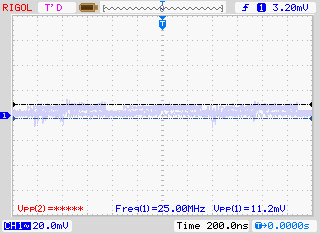
Below, please find measurements of the remaining ripple and noise. The output voltage shows practically no ripple (less than 12mV Peak-to-Peak), the input voltage very little (ca. 66 mV Peak-to-Peak).
The parameters of the measurement were as follows:
Input voltage: 9V from a 9V block battery.
Load: 100 R resistor
Output voltage: 11.9V
Output current: 119 mA
Measurements taken with a DMM and a Rigol Oscilloskope with a 1.10 probe.
Input Voltage Ripple and Noise:

Output Voltage Ripple and Noise:
An Excel file that can be uploaded to Mouser's BOM tool is included in the repository at
https://github.com/mfhepp/gobox-power/raw/master/hardware/go-box-power.xlsx
Note: This is a densely packed PCB design using SMD components in size 0603, and for minimizing EMI, the pads do not have thermal relief, i.e. are directly connected to the copper of the ground signal and other signals. This makes soldering a bit challenging, and reworking even more so. In other words, this should not be your first exercise in SMD soldering....
The components are placed with minimal distances, so when hand-soldering, you need to think carefull about the ordering of components. Some pads will become hard to reach for hand-soldering once the adjacent component will have been added.
Because of the lack of thermal relief and the pads, you need to use a higher soldering temperature (I found 400 °C to work well), but this in turn means you have to work swiftly. I recommend a flat 1.2mm tip and a round 0.4 mm tip for the work. Preheating the PCB might be a good idea. You also need the finest rosin-core solder you can get hold of.
The files in the repository contain
KiCad is a great and free electronics design package. For more information, see http://kicad-pcb.org/.
tbd
THE SOFTWARE AND DESIGN ARE PROVIDED "AS IS", WITHOUT WARRANTY OF ANY KIND, EXPRESS OR IMPLIED, INCLUDING BUT NOT LIMITED TO THE WARRANTIES OF MERCHANTABILITY, FITNESS FOR A PARTICULAR PURPOSE AND NONINFRINGEMENT. IN NO EVENT SHALL THE AUTHORS OR COPYRIGHT HOLDERS BE LIABLE FOR ANY CLAIM, DAMAGES OR OTHER LIABILITY, WHETHER IN AN ACTION OF CONTRACT, TORT OR OTHERWISE, ARISING FROM, OUT OF OR IN CONNECTION WITH THE SOFTWARE OR DESIGN OR THE USE OR OTHER DEALINGS IN THE SOFTWARE OR DESIGN.
| Qty | Value | Footprint | References |
|---|---|---|---|
| 4 | 10u/25V | Capacitors_SMD:C_0805 | C3, C4, C5, C6 |
| 3 | 4.7u/2A | Choke_SMD:Choke_SMD_7.3x7.3_H4.5 | L1, L2, L3 |
| 2 | 220 | Resistors_SMD:R_0603 | R8, R10 |
| 2 | BC847 | TO_SOT_Packages_SMD:SOT-23 | Q1, Q2 |
| 1 | 1.2M | Resistors_SMD:R_0603 | R5 |
| 1 | 100k | Resistors_SMD:R_0603 | R1 |
| 1 | 10k | Resistors_SMD:R_0603 | R7 |
| 1 | 10u/25V | Capacitors_SMD:CP_Elec_4x5.8 | C8 |
| 1 | 15p | Capacitors_SMD:C_0603 | C7 |
| 1 | 1N5822 | mfhepp:not_on_board | D1 |
| 1 | 1k | Resistors_SMD:R_0603 | R6 |
| 1 | 2.1MM | mfhepp:not_on_board | EXT_BATTERY1 |
| 1 | 2.5MM | mfhepp:not_on_board | CHARGE1 |
| 1 | 33u/16V low ESR | Capacitors_SMD:CP_Elec_6.3x5.3 | C1 |
| 1 | 360k | Resistors_SMD:R_0603 | R4 |
| 1 | 4.8V 4-cell NiMH Battery | mfhepp:not_on_board | BT1 |
| 1 | 430k | Resistors_SMD:R_0603 | R2 |
| 1 | 47k | Resistors_SMD:R_0603 | R9 |
| 1 | 47u/16V | Capacitors_SMD:CP_Elec_5x5.8 | C2 |
| 1 | 51k | Resistors_SMD:R_0603 | R3 |
| 1 | BZX84-3.9V | TO_SOT_Packages_SMD:SOT-23 | D3 |
| 1 | DC_JACK | mfhepp:Generic_2-Pin_Connector_0.8mm | J1 |
| 1 | ON | mfhepp:not_on_board | SW1 |
| 1 | PWR_LEVEL | mfhepp:SW2-3pins | SW2 |
| 1 | Polyfuse 1.85/3A | mfhepp:not_on_board | F1 |
| 1 | RIG_GND | Wire_Pads:SolderWirePad_3x_0-8mmDrill | J3 |
| 1 | RIG_VCC | Wire_Pads:SolderWirePad_3x_0-8mmDrill | J2 |
| 1 | SC4503 | TO_SOT_Packages_SMD:TSOT-23-5 | U1 |
| 1 | SS14L | mfhepp:D_SubSMA | D2 |
| 1 | green | lib_fr:LED_D3.0mm-external | PWR1 |
| 1 | red | lib_fr:LED_D3.0mm-external | LOW1 |
The 38 most common of 52 parts.

acha666/RP2040_ToolheadPCB_SB
A Toolhead PCB for VORON StealthBurner based on RP2040

EDA-bench/eda-bench
Execution-based benchmark for open-book KiCad PCB reconstruction agents

madworm/IKEA-Samtid_mood-light
LAYOUT FILES: Circular extension board for IKEA Samtid lamps.

actuallysparky/bearamin
Bear-sized optical gesture instrument firmware.


Ardumower/ardumower
Develop an open source robotic lawn mower (HW+SW reference platform)

It measures 41.9 × 22.2 mm and has 2 copper layers, 1.6 mm thick.
52 parts, built around the BC847 and SS14L. The full list of its parts is on this page, with links to each part's symbol and footprint where PCBKit's library has them.
From the mfhepp/gobox-power repository on GitHub, at the commit this page was made from: the board is hardware/go-box-power.kicad_pcb. PCBKit opens the board in the browser, with nothing to install.
Its repository states no licence, so its author keeps all rights: ask mfhepp before reusing the design.