4 layers81 × 14 mm

 mayashapiro19/table-zamboni
Peripherals is an open-source printed circuit board by mayashapiro19, from the mayashapiro19/table-zamboni repository on GitHub. It is a 4-layer board of 36.5 × 23.5 mm with 24 parts on 14 nets.
It is built around the 74AHCT1G125SE, TPD1E05U06DPY and TPS22918DBV, with the D6R90 F2 LFS and WS2812B among its other parts. Its parts include 6 capacitors, 6 resistors, 4 diodes, 2 ICs and 1 connector.


The image below shows a high-level block diagram of the hardware architecture.
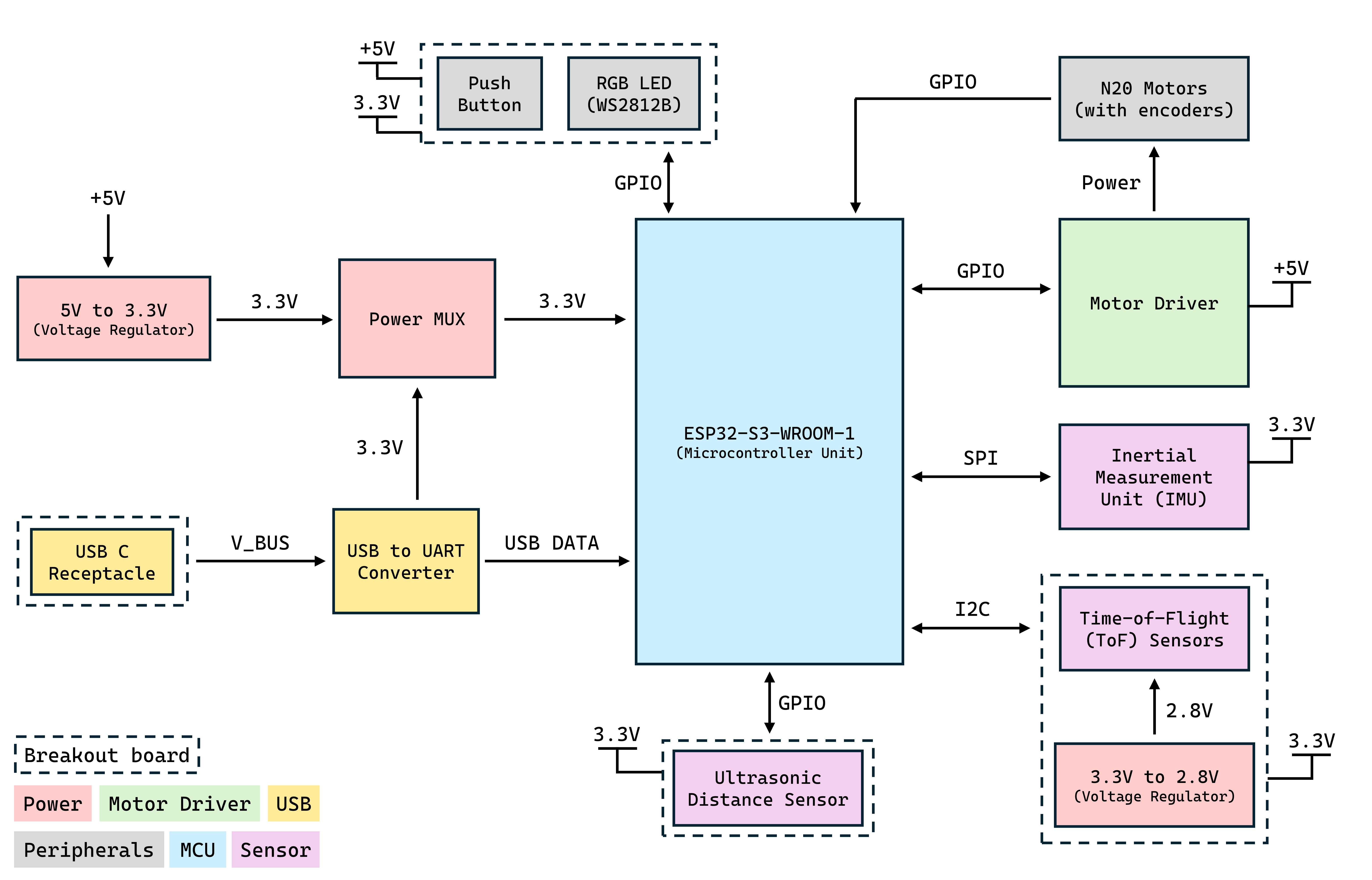
The main PCB uses an ESP32-S3-WROOM-1-N8 module and includes power management circuitry, a USB to UART converter, motor driver, and an inertial measurement unit.
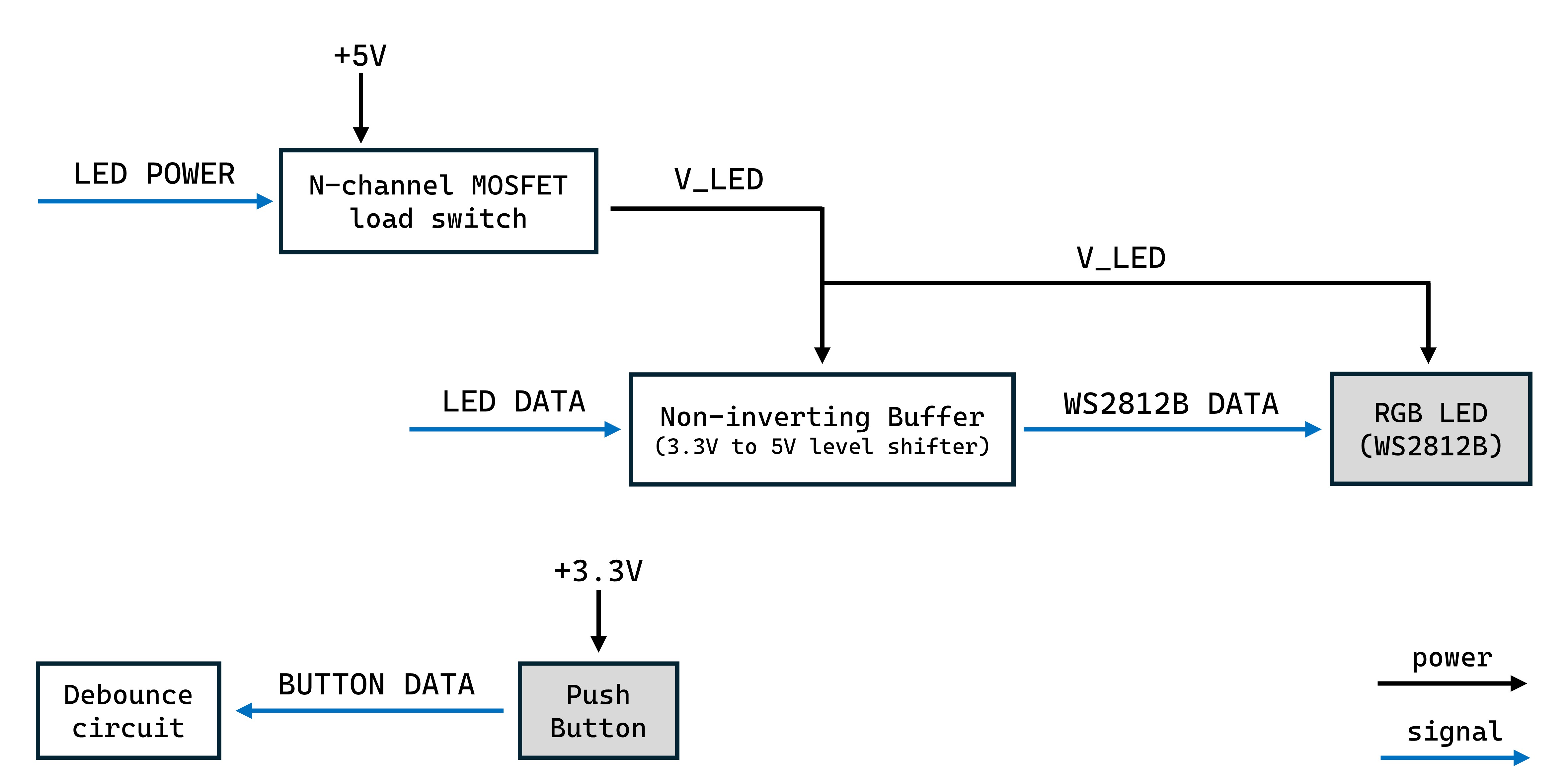
The peripherals breakout board includes a push button and a WS2812B LED. The LED will be used at specific points to communicate things to the user. Because it will only be used for short periods of time, to save power, a load switch is used. The block diagram below illustrates the hardware architecture of the peripherals breakout board.
| Qty | Value | Footprint | References |
|---|---|---|---|
| 4 | MountingHole | MountingHole:MountingHole_3mm | H1, H2, H3, H4 |
| 2 | 0.1uF | Capacitor_SMD:C_0805_2012Metric_Pad1.18x1.45mm_HandSolder | C4, C6 |
| 2 | 1uF | Capacitor_SMD:C_0805_2012Metric_Pad1.18x1.45mm_HandSolder | C1, C5 |
| 2 | 220Ω | Resistor_SMD:R_0805_2012Metric_Pad1.20x1.40mm_HandSolder | R3, R5 |
| 2 | TPD1E6B06 | TPD1E6B06:TPD1E6B06_footprint | D1, D3 |
| 1 | 10k | Resistor_SMD:R_0805_2012Metric_Pad1.20x1.40mm_HandSolder | R4 |
| 1 | 10Ω | Resistor_SMD:R_0805_2012Metric_Pad1.20x1.40mm_HandSolder | R2 |
| 1 | 220pF | Capacitor_SMD:C_0805_2012Metric_Pad1.18x1.45mm_HandSolder | C3 |
| 1 | 22pF | Capacitor_SMD:C_0805_2012Metric_Pad1.18x1.45mm_HandSolder | C2 |
| 1 | 330Ω | Resistor_SMD:R_0805_2012Metric_Pad1.20x1.40mm_HandSolder | R6 |
| 1 | 58.3Ω | Resistor_SMD:R_0805_2012Metric_Pad1.20x1.40mm_HandSolder | R1 |
| 1 | 74AHCT1G125 | 74AHCT1G125D:DBV5-M | U2 |
| 1 | Conn_01x06 | Connector_JST:JST_SH_BM06B-SRSS-TB_1x06-1MP_P1.00mm_Vertical | J1 |
| 1 | D6R90F2LFS | D6R90F2LFS:D6R90_CNK | SW1 |
| 1 | TPD1E05U06 | TPD1E05U06:TPD1E05U06 | D2 |
| 1 | TPS22918 | TPS22918DBVT:DBV6_TEX-M | U1 |
| 1 | WS2812B | WS2812B:COM-16347_SPK-M | D4 |


salvatore999uwo/mini_hvac_v2
Second version of the temperature control system for a small model room.


It measures 36.5 × 23.5 mm and has 4 copper layers, 1.6 mm thick.
24 parts, built around the 74AHCT1G125SE, TPD1E05U06DPY, TPS22918DBV and D6R90 F2 LFS. The full list of its parts is on this page, with links to each part's symbol and footprint where PCBKit's library has them.
From the mayashapiro19/table-zamboni repository on GitHub, at the commit this page was made from: the board is Peripherals_PCB/peripherals.kicad_pcb and its schematic Main_PCB/drive_motors.kicad_sch. PCBKit opens the board in the browser, with nothing to install.
Its repository states no licence, so its author keeps all rights: ask mayashapiro19 before reusing the design.