4 layers53.5 × 53.5 mm
MiniTULPAR
ErdemHtyl/Tulpar_Mini_FCB
This project is under active development. The table below shows what is finished and what is still in progress:
92 partsBSD-3-Clause

 marcoallegretti/Teresina-Rack
The goal is an open, self-fabricatable Daisy Patch SM-compatible Eurorack submodule: the same carrier interface and libDaisy application compatibility through a small Teresina firmware variant.
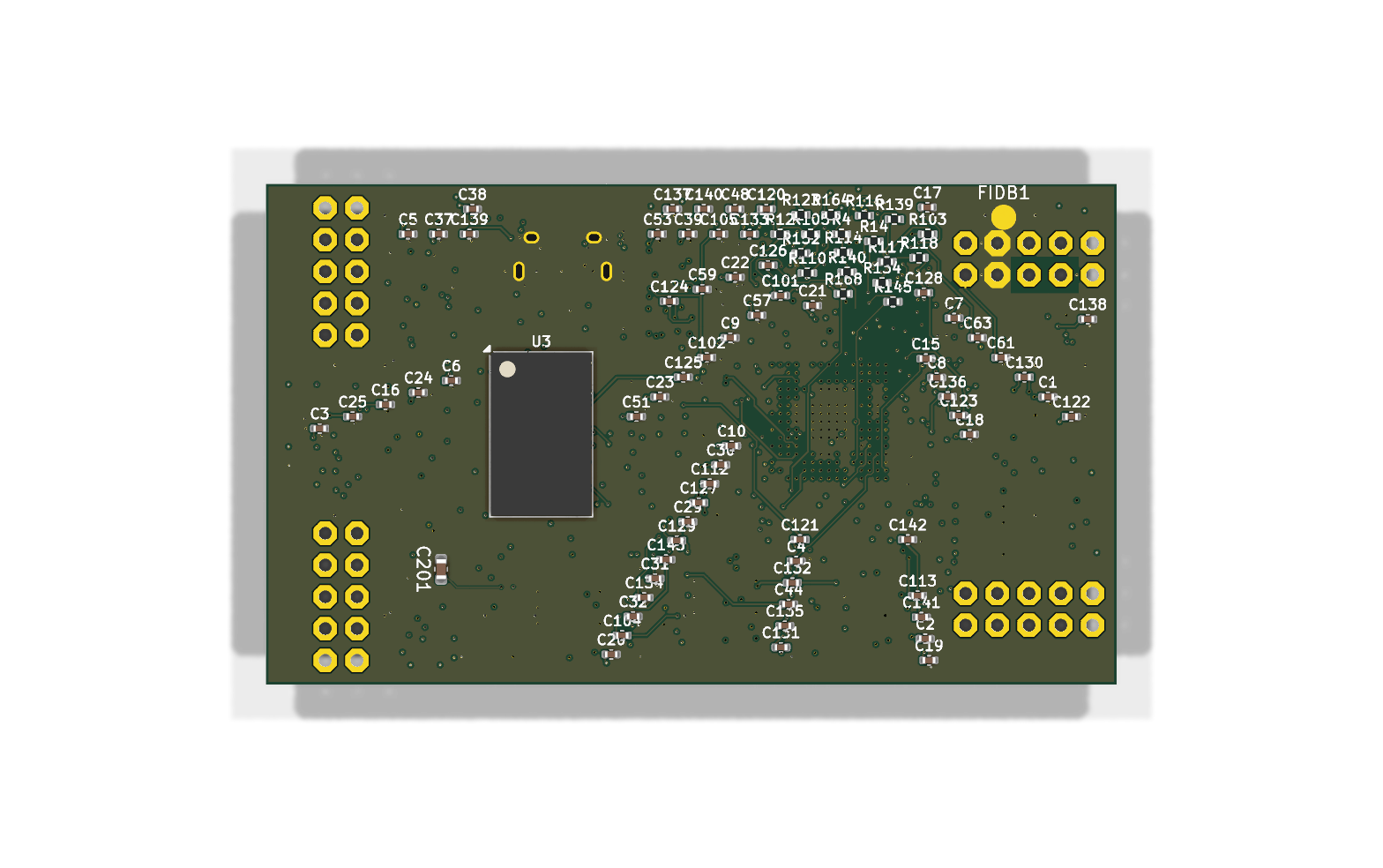
Teresina Rack is an open-source printed circuit board by marcoallegretti, from the marcoallegretti/Teresina-Rack repository on GitHub. It is a 12-layer board of 68 × 40 mm with 214 parts on 205 nets, routed with 5,172 tracks and 829 vias.
It is built around the STM32H750IBK6, MCP6004T-I/SL(MS) and IS25LP064A-JBLE, with the PCM3060PW, TL074IDT and IS42S32160F-6BLI among its other parts. Its parts include 96 capacitors, 80 resistors, 12 ICs, 5 diodes and 3 connectors. It belongs with the STM32 boards of this library.


Version 0.1.0-alpha0 — under engineering review; not fabricated or hardware-tested. The current PCB is a 12-layer baseline with confirmed electrical, BOM, package and layout findings. It is not approved for production.
The goal is an open, self-fabricatable Daisy Patch SM-compatible Eurorack submodule: the same carrier interface and libDaisy application compatibility through a small Teresina firmware variant. Source compatibility and hardware behavior remain qualification targets. See the firmware policy and production review.
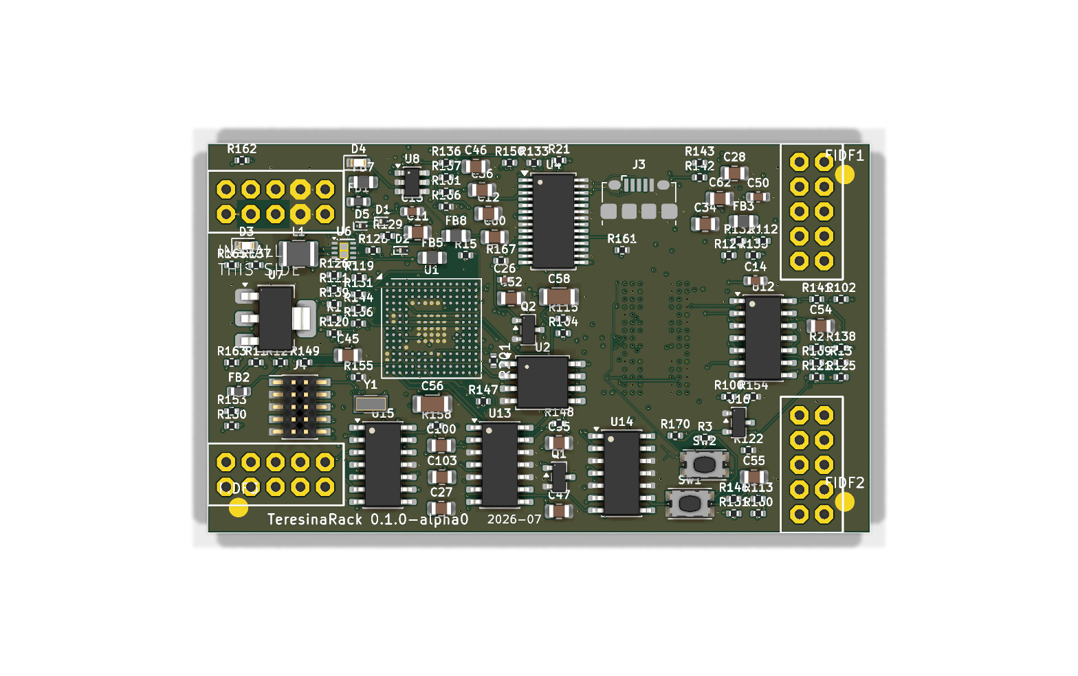
| Top | Bottom |
|---|---|
|  |
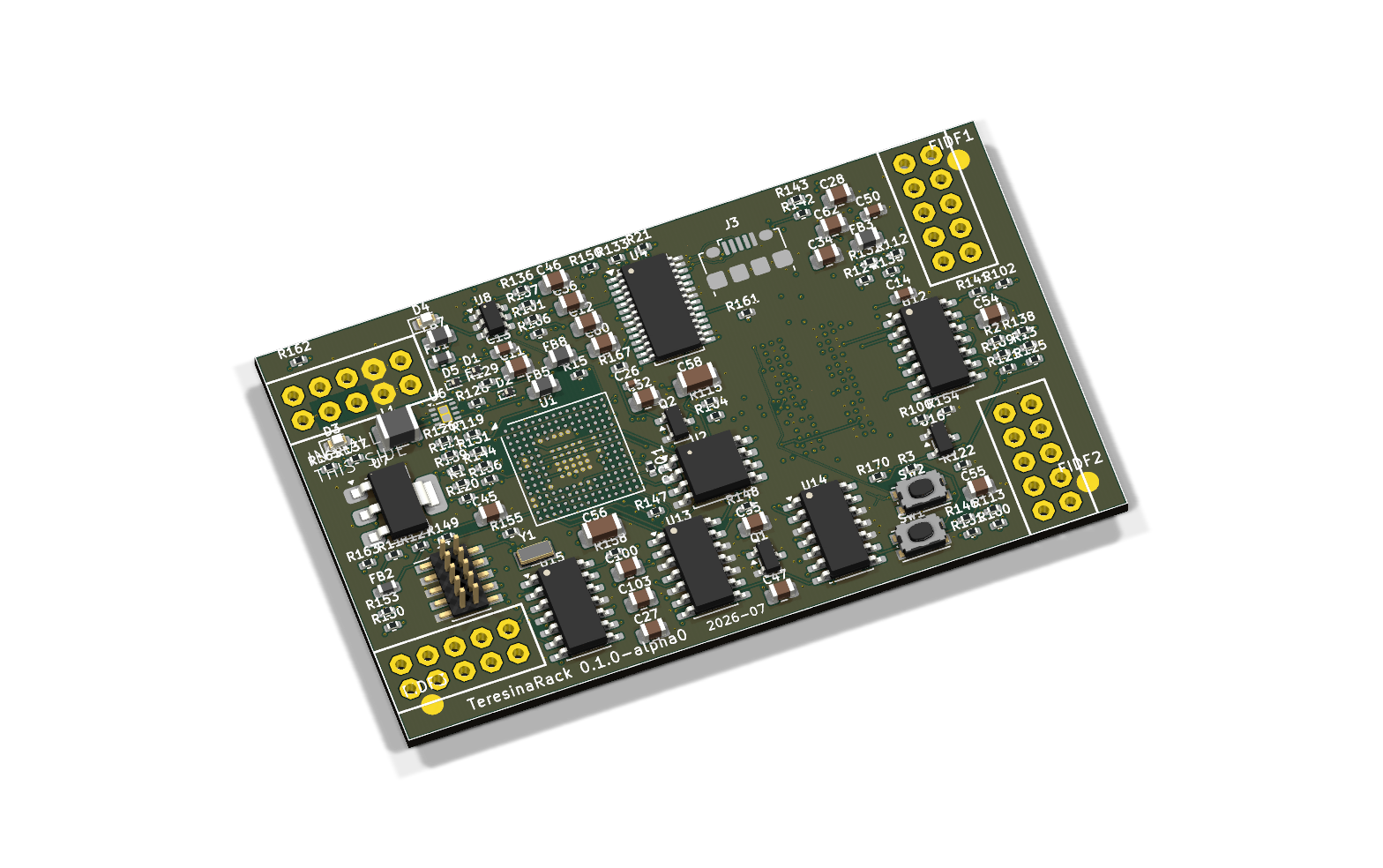
4 copper layers preferred; 6 acceptable if required; 8 the final fallback. Evaluate in that order with new placement, BGA escape, timing, return-path and manufacturer review. Document the constraint and alternatives tried before increasing layer count. Twelve layers describe the existing file only and are outside the redesign target. See the redesign plan.
Disposable four-layer MCU escape trials reached zero native clearance errors when six power-pad vias were filled/capped. The full board remains unrouted in those studies, and SDRAM escape at the inherited placement still fails. These results do not qualify a four-layer production design.
| Block | Baseline |
|---|---|
| Interface | 68 × 40 mm, 40 through-hole mating pads; all 40 local pad geometries match official CAD |
| MCU | STM32H750IBK6, UFBGA176+25 balls, 480 MHz Cortex-M7 |
| RAM | IS42S32160F-6BLI prototype candidate, 64 MB, 3.3 V, 32-bit FMC; requires the Teresina refresh profile and hardware qualification |
| Flash | IS25LP064A, 8 MB QSPI |
| Codec | PCM3060, SAI1, I²C2 address 0x46 |
| Analog | TL074 audio, MCP6004 CV/gates, LM4040-10 V reference |
| Power | TPS62170 digital buck, LD1117 5 V stage; component selection/layout/budgets require correction |
| Files | 209 schematic component references, 214 PCB footprints including five fiducials |
Manufacturer pin maps confirm the core/codec/analog signal assignments. 74 checked digital-net assignments agree with pinned libDaisy. Complete carrier fit, sequencing, analog performance and firmware execution still need first-article validation.
Official libDaisy v9.0.0 is the pinned firmware reference. Its stock refresh sweep is 168.35 ms against the proposed ISSI part's 64 ms requirement. An opt-in Teresina prototype now implements a conservative refresh profile and reviewed clock/init changes. Crossbuilds support a limited source-compatibility claim; stock binaries are unsupported and hardware tests remain unrun. See the firmware decision and original retention check.
An expanded memory-replacement search found no datasheet-backed fix for unchanged firmware. Etron EM63B325BK is an unresolved catalogue lead; it has not been qualified or selected.
The review also confirms wrong ferrite/inductor/capacitor ordering data, crystal/diode footprint mismatches, CV amplifiers on the wrong supply, gate-output resistance differences and remote critical power/clock/decoupling loops. The earlier claims of an identical analog implementation and completed production validation are superseded by the current findings. Reviewed corrections are staged outside the checkout until the complete design can be synchronized.
| Check | Baseline result and boundary |
|---|---|
| Native KiCad 10.0.7 DRC | 0 errors, 0 unconnected, 414 warnings |
| Native ERC | 3 power-pin conflicts, 250 warnings; unresolved |
| Native netlist→PCB | 821 functional pad assignments agree; intentional NC aliases separately checked |
| Connectivity | 200 routed nets connected; native zone-refill agreement |
| Copper hygiene | 384 candidate findings; requires geometric review |
| SPICE | 63 generated tests pass; ideal channel benches also executed; device/rail/tolerance coverage incomplete |
| EMC/thermal | Risk analyses executed; thermal budget incomplete; no compliance measurement |
| Fabrication export | 34 Gerbers, PTH/NPTH drills, CPL; baseline only |
A clean native DRC does not resolve wrong ordered parts or prove stock-firmware retention, thermal safety, analog performance or carrier fit. See the full review for passed, failed and unrun checks.
Use KiCad 10 for the project under TeresinaRack/. The configured cloud environment retains checksum-verified KiCad 10.0.7, ngspice 47, kicad-tools, KiCadRoutingTools and kicad-happy; reproducible setup/startup instructions are saved in environment settings. Interactive GUI editing and hardware programming were not validated in the headless environment.
Keep every routing operation's before/after evidence and run native DRC/refill, independent connectivity and copper hygiene before accepting it. Use the actual selected JLCPCB process, not an unrelated generic profile. Final fabrication requires an accepted stackup, explicit filled/capped-via process, corrected sourcing-complete BOM, CPL/assembly drawings, header dimensions and first-article plan. The current files and exports are not an approved order package.
kicad-cli pcb drc --format json -o drc.json TeresinaRack.kicad_pcb
kicad-cli sch erc --format json -o erc.json TeresinaRack.kicad_sch
Run from TeresinaRack/ and inspect every report severity and unconnected item. Exit 0 alone does not establish a pass. Generated fabrication files belong in the ignored fab/ directory.
TeresinaRack/: editable KiCad project, custom symbols and rules.docs/production-review.md: current evidence, blockers and review limits.docs/redesign-plan.md: requirements, 4 → 6 → 8 sequence and acceptance gates.docs/review/: inventory, calculations and independent subsystem evidence.DESIGN.md: historical working notes, superseded by the current review.bom/: baseline BOM working files; not approved production sourcing.This is an independent DIY project, not affiliated with or endorsed by Electro-Smith. "Daisy" and "Patch SM" are their marks. Build at your own risk — check everything before powering your rack.
| Qty | Value | Footprint | References |
|---|---|---|---|
| 45 | 100nF | Capacitor_SMD:C_0402_1005Metric | C1, C2, C10, C16, C18, C19, C20, C102, C105, C112, C113, C140, C141, C142, C143, C202 +29 |
| 12 | 100K | Resistor_SMD:R_0402_1005Metric | R124, R125, R126, R127, R128, R129, R130, R131, R160, R161, R164, R165 |
| 12 | 1K | Resistor_SMD:R_0402_1005Metric | R102, R105, R148, R149, R150, R151, R152, R153, R162, R163, R202, R203 |
| 10 | 10uF | Capacitor_SMD:C_0805_2012Metric | C34, C35, C45, C47, C52, C54, C55, C60, C62, C203 |
| 10 | 220pF | Capacitor_SMD:C_0402_1005Metric | C101, C104, C126, C127, C128, C129, C130, C131, C132, C133 |
| 8 | 200K | Resistor_SMD:R_0402_1005Metric | R132, R133, R134, R135, R136, R137, R138, R139 |
| 8 | 33K | Resistor_SMD:R_0402_1005Metric | R140, R141, R142, R143, R144, R145, R146, R147 |
| 6 | 18pF | Capacitor_SMD:C_0402_1005Metric | C37, C38, C120, C122, C123, C125 |
| 6 | 1nF | Capacitor_SMD:C_0402_1005Metric | C134, C135, C136, C137, C138, C139 |
| 6 | 66K5 | Resistor_SMD:R_0402_1005Metric | R100, R103, R111, R114, R118, R121 |
| 5 | 600R@100MHz | Inductor_SMD:L_0805_2012Metric | FB3, FB5, FB7, FB8, FB9 |
| 5 | Fiducial_1mm_Mask2mm | Fiducial_1mm_Mask2mm | FIDB1, FIDB2, FIDF1, FIDF2, FIDF3 |
| 4 | 100R | Resistor_SMD:R_0402_1005Metric | R116, R123, R158, R159 |
| 4 | 18K | Resistor_SMD:R_0402_1005Metric | R110, R113, R117, R120 |
| 4 | 39K | Resistor_SMD:R_0402_1005Metric | R112, R115, R119, R122 |
| 4 | 4.7uF | Capacitor_SMD:C_0805_2012Metric | C11, C12, C27, C28 |
| 3 | 10k | Resistor_SMD:R_0402_1005Metric | R3, R4, R21 |
| 3 | 1uF | Capacitor_SMD:C_0402_1005Metric | C15, C17, C48 |
| 3 | 2.2uF | Capacitor_SMD:C_0603_1608Metric | C13, C14, C50 |
| 3 | MCP6004 | Package_SO:SOIC-14_3.9x8.7mm_P1.27mm | U13, U14, U15 |
| 3 | NSR1020 | Diode_SMD:D_SOD-923 | D1, D2, D5 |
| 2 | 100pF | Capacitor_SMD:C_0402_1005Metric | C121, C124 |
| 2 | 10K | Resistor_SMD:R_0402_1005Metric | R168, R169 |
| 2 | 120K | Resistor_SMD:R_0402_1005Metric | R154, R155 |
| 2 | 15K | Resistor_SMD:R_0402_1005Metric | R101, R104 |
| 2 | 1M | Resistor_SMD:R_0402_1005Metric | R166, R167 |
| 2 | 1k | Resistor_SMD:R_0402_1005Metric | R14, R15 |
| 2 | 2.2uF | Capacitor_SMD:C_0805_2012Metric | C100, C103 |
| 2 | 22uF | Capacitor_SMD:C_1206_3216Metric | C56, C58 |
| 2 | 22uF | Capacitor_SMD:C_0805_2012Metric | C36, C46 |
| 2 | 4.7k | Resistor_SMD:R_0402_1005Metric | R1, R2 |
| 2 | 600R@100MHz | Inductor_SMD:L_0603_1608Metric | FB1, FB2 |
| 2 | 62K | Resistor_SMD:R_0402_1005Metric | R156, R157 |
| 2 | MMBT3904 | Package_TO_SOT_SMD:SOT-23 | Q1, Q2 |
| 1 | 15k | Resistor_SMD:R_0402_1005Metric | R13 |
| 1 | 16MHz | Crystal:Crystal_SMD_3215-2Pin_3.2x1.5mm | Y1 |
| 1 | 2.2uF | C_0603_1608Metric | C201 |
| 1 | 2.2uH | Inductor_SMD:L_1210_3225Metric | L1 |
| 1 | 2K | Resistor_SMD:R_0402_1005Metric | R170 |
| 1 | 47k | Resistor_SMD:R_0402_1005Metric | R12 |
| 1 | 4K7 | R_0402_1005Metric | R201 |
| 1 | 5.1R | Resistor_SMD:R_0402_1005Metric | R11 |
| 1 | BOOT | Button_Switch_SMD:SW_Push_1P1T_NO_CK_KMR2 | SW2 |
| 1 | IS25LP064A | Package_SO:SOIC-8_5.3x5.3mm_P1.27mm | U2 |
| 1 | IS42S32160F-6BLI | Package_BGA:BGA-90_8.0x13.0mm_Layout2x3x15_P0.8mm | U3 |
| 1 | LD1117S50 | Package_TO_SOT_SMD:SOT-223-3_TabPin2 | U7 |
| 1 | LED_PWR | LED_SMD:LED_0603_1608Metric | D4 |
| 1 | LED_USER | LED_SMD:LED_0603_1608Metric | D3 |
| 1 | LM4040DBZ-10 | Package_TO_SOT_SMD:SOT-23 | U16 |
| 1 | PATCH_SM_EDGE | TeresinaRack:DAISY_PATCH_SM | J5 |
| 1 | PCM3060 | Package_SO:TSSOP-28_4.4x9.7mm_P0.65mm | U4 |
| 1 | RESET | Button_Switch_SMD:SW_Push_1P1T_NO_CK_KMR2 | SW1 |
| 1 | STM32H750IBK6 | Package_BGA:UFBGA-201_10x10mm_Layout15x15_P0.65mm | U1 |
| 1 | SWD | Connector_PinHeader_1.27mm:PinHeader_2x05_P1.27mm_Vertical_SMD | J4 |
| 1 | TL074 | Package_SO:SOIC-14_3.9x8.7mm_P1.27mm | U12 |
| 1 | TPS62170DSGR | Package_SON:Texas_DSG0008A_WSON-8-1EP_2x2mm_P0.5mm_EP0.9x1.6mm | U6 |
| 1 | USBLC6-2SC6 | Package_TO_SOT_SMD:SOT-23-6 | U8 |
| 1 | USB_Micro-B | Connector_USB:USB_Micro-B_Amphenol_10118194-0001LF_Horizontal | J3 |
ErdemHtyl/Tulpar_Mini_FCB
This project is under active development. The table below shows what is finished and what is still in progress:


igorwolfs/modular-processing-hw
MCU Breakout board with Hirose BM28B connector


MidwestMotorBoy/Battery-Bank
Monolith: an ultralight IP67 power bank for backpacking. 4S BAK 65E 21700 (91 Wh, under the 100 Wh airline limit), two bidirectional 100 W USB-C PD ports, Bluetooth LE (TI CC2340) with an iPhone app.

lepton-7/Open-Plate-Spectrophotometer
An open-source project to build a 96-well spectrophotometer operating at 620nm. Designed from the ground-up focusing on robust electronic design.
It measures 68 × 40 mm and has 12 copper layers, 1.6 mm thick.
214 parts, built around the STM32H750IBK6, MCP6004T-I/SL(MS), IS25LP064A-JBLE and PCM3060PW. The full list of its parts is on this page, with links to each part's symbol and footprint where PCBKit's library has them.
From the marcoallegretti/Teresina-Rack repository on GitHub, at the commit this page was made from: the board is TeresinaRack/TeresinaRack.kicad_pcb and its schematic TeresinaRack/TeresinaRack.kicad_sch. PCBKit opens the board in the browser, with nothing to install.
Its repository states no licence, so its author keeps all rights: ask marcoallegretti before reusing the design.