
2 layers47.9 × 51 mm

 mage0r/Solder-Kits6
Simple How to Solder Badge Kit
Badge kit is an open-source printed circuit board by mage0r, from the mage0r/Solder-Kits repository on GitHub. It is a 2-layer board of 38 × 48.9 mm with 7 parts on 4 nets, routed with 14 tracks and 0 vias.
It is built around the CR2032. Its parts include 2 diodes, 2 connectors and 1 switch. It belongs with the lEDs and displays boards of this library.
In the great tradition of hackerspaces everwhere, CCHS runs frequent, simple, "how to solder" courses for kids of all ages.
Our previous kit was designed by Luke Weston and had a very similar schematic. This one has been updated for parts availability and in order to have a more "fun" board.
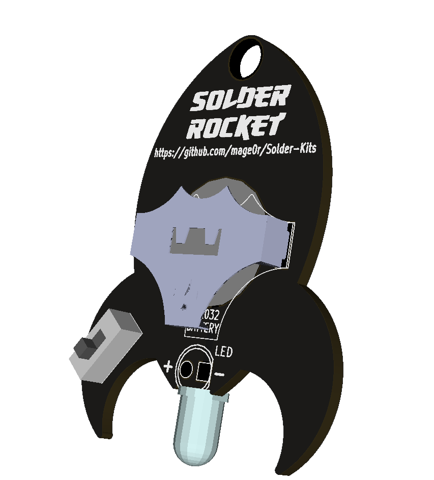
The "Rocket" outline was designed in Sketchup and exported as a dxf to be inputed in to KiCAD.
The "Solder Rocket" text was generated using simple text tools and imported using bitmap2component.
This updated design uses a metal battery holder. This part does become hot during soldering but should cool quickly.
Tronixlabs is currently stocking these kits in packs of 3.
https://tronixlabs.com.au/kits/solder-rocket-learn-to-solder-kit-triple-pack-tronixlabs-australia/
This project was designed by John Spencer
Made at hackmelbourne.org!
To the HackMelbourne (CCHS, http://hackmelbourne.org) community of Melbourne, Australia.
To all other open-source developers whose countless hours supported every other aspect of this design.
The specific terms of distribution of this project are governed by the license referenced below. Please contact the copyright owner if you wish to modify the board for distribution. Please utilize this design for personal or research projects. Please acknowledge all contributors.
Licensed under the TAPR Open Hardware License (www.tapr.org/OHL). A plain text version of this license is included in this directory.
Copyright John Spencer 2018
| Qty | Value | Footprint | References |
|---|---|---|---|
| 2 | LED | LEDs:LED-5MM | D1, D1 |
| 1 | CR2032 | badge-kit:CR2032 | BT1 |
| 1 | LOGO | badge-kit:solder-rocket | J1 |
| 1 | LOGO_SMALL | badge-kit:solder-rocket-small | J2 |
| 1 | ON/OFF | badge-kit:SS12D00 | SW2 |
| 1 | val** | freetronics_footprints:1pin_prototyping | 1pin_prototyping |


skiselev/zeta_sbc
Zeta SBC is an Zilog Z80 based single board computer. It is inspired by Ampro Little Board Z80 and N8VEM project. Zeta SBC is software compatible with RomWBW Firmware
It measures 38 × 48.9 mm and has 2 copper layers, 1.6 mm thick.
7 parts, built around the CR2032. The full list of its parts is on this page, with links to each part's symbol and footprint where PCBKit's library has them.
From the mage0r/Solder-Kits repository on GitHub, at the commit this page was made from: the board is Solder Rocket/badge-kit.kicad_pcb. PCBKit opens the board in the browser, with nothing to install.
Its repository states no licence, so its author keeps all rights: ask mage0r before reusing the design.
