

2 layers51.3 × 96.2 mm
Minisynth32
grantek/minisynth32
A 3D-printable MIDI synthesiser inspired by the Roland MT-32 and clumsyMIDI, and powered by the mt32-pi MT-32 emulator.
32 parts45CC-BY-SA-4.0

 LucasFM-EE/PBLE01_PCB
Project designed for the discipline: Project Based Learning 01.
PBLE01 is an open-source printed circuit board by LucasFM-EE, from the LucasFM-EE/PBLE01_PCB repository on GitHub. It is a 2-layer board of 80 × 80 mm with 65 parts on 100 nets, routed with 562 tracks and 38 vias.
It is built around the LM324 and PJ-002A. Its parts include 20 resistors, 16 capacitors, 7 connectors, 6 switches and 5 ICs. It belongs with the PIC boards of this library.
Project designed for the discipline: Project Based Learning 01.
In this project, the board must match these requirements:
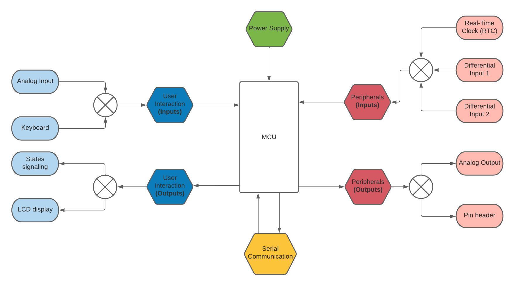
The following image shows a functional diagram of the board:
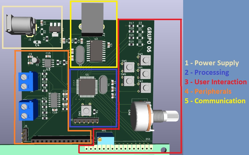
The following image shows the board, divided by the sections mentioned above:
| Qty | Value | Footprint | References |
|---|---|---|---|
| 9 | 330 | Resistor_SMD:R_0805_2012Metric_Pad1.20x1.40mm_HandSolder | R2, R7, R8, R11, R12, R17, R18, R19, R20 |
| 6 | 100nF | Capacitor_SMD:C_0805_2012Metric_Pad1.18x1.45mm_HandSolder | C3, C6, C13, C14, C15, C16 |
| 6 | 1825910-6 | Chave Táctil:SW_1825910-6-4 | SW1, SW2, SW3, SW4, SW5, SW6 |
| 5 | LED | LED:LTST-C150GKT | D2, D3, D4, D5, D6 |
| 4 | 10k | Resistor_SMD:R_0805_2012Metric_Pad1.20x1.40mm_HandSolder | R1, R4, R5, R6 |
| 4 | 1k | Resistor_SMD:R_0805_2012Metric_Pad1.20x1.40mm_HandSolder | R9, R10, R13, R14 |
| 2 | 10pF | Capacitor_SMD:C_0805_2012Metric_Pad1.18x1.45mm_HandSolder | C9, C10 |
| 2 | 15pF | Capacitor_SMD:C_0805_2012Metric_Pad1.18x1.45mm_HandSolder | C1, C2 |
| 2 | 22pF | Capacitor_SMD:C_0805_2012Metric_Pad1.18x1.45mm_HandSolder | C7, C8 |
| 2 | C | Capacitor_SMD:C_0805_2012Metric_Pad1.18x1.45mm_HandSolder | C11, C12 |
| 2 | R | Resistor_SMD:R_0805_2012Metric_Pad1.20x1.40mm_HandSolder | R15, R16 |
| 2 | Screw_Terminal_01x02 | TerminalBlock_MetzConnect:TerminalBlock_MetzConnect_Type011_RT05502HBWC_1x02_P5.00mm_Horizontal | J4, J5 |
| 1 | 10k | Potentiometer_THT:Potentiometer_Bourns_3296W_Vertical | RV1 |
| 1 | 10uF | SamacSys_Parts:CAPPM3216X180N | C4 |
| 1 | 12MHz | Crystal:Crystal_HC49-4H_Vertical | Y2 |
| 1 | 20MHz | Crystal:Crystal_HC49-4H_Vertical | Y1 |
| 1 | 220nF | Capacitor_SMD:C_0805_2012Metric_Pad1.18x1.45mm_HandSolder | C5 |
| 1 | 32.768kHz | SamacSys_Parts:XTAL_AB38T-32.768KHZ | Y3 |
| 1 | 470 | Resistor_SMD:R_0805_2012Metric_Pad1.20x1.40mm_HandSolder | R21 |
| 1 | Conn_01x03_Male | Connector_PinHeader_2.54mm:PinHeader_1x03_P2.54mm_Vertical | J6 |
| 1 | Conn_01x14_Female | Connector_PinSocket_2.54mm:PinSocket_1x14_P2.54mm_Vertical | J7 |
| 1 | HY1602E | Display:HY1602E | DS1 |
| 1 | ICSP | Connector_PinHeader_2.54mm:PinHeader_1x06_P2.54mm_Vertical | J1 |
| 1 | LD1117S50TR_SOT223 | Package_TO_SOT_SMD:SOT-223-3_TabPin2 | U5 |
| 1 | LM324 | SamacSys_Parts:SOIC127P600X175-14N | U4 |
| 1 | MCP2200-I-SO | Package_SO:SOIC-20W_7.5x12.8mm_P1.27mm | U2 |
| 1 | MCP7940N-xSN | SamacSys_Parts:SOIC127P600X175-8N | U3 |
| 1 | PIC18F4550-IPT | Package_QFP:TQFP-44_10x10mm_P0.8mm | U1 |
| 1 | PJ-002A | PJ-002A:CUI_PJ-002A | J2 |
| 1 | R_POT | SamacSys_Parts:P160KN0QC15B100K | RV2 |
| 1 | USB | SamacSys_Parts:8974300490000000 | J3 |
grantek/minisynth32
A 3D-printable MIDI synthesiser inspired by the Roland MT-32 and clumsyMIDI, and powered by the mt32-pi MT-32 emulator.

thewonderidiot/lachesis
Portable, safe readers for Apollo Guidance Computer core rope memory modules

jrowe88/RPi-LED-RGBMatrix-Hat
Hardware hat for Raspberry Pi to support RGB Matrix and LED strips

scott-whitworth/bancroft_temperature_control
Supplementary material for Bancroft Experimental Temperature Control System

cegep-electronique-programmable/pcb_alimentation_prototypage
Cette carte génére une tension de 3.3V ou 5V et se branche sur une plaquette de prototypage (breadboard).


alighieribot/lpc11u14-board-bringup
Board bring-up, hardware debugging & validation, and event-driven bare-metal firmware (ARM Cortex-M0 LPC11U14F) | UNIFEI PBLE02
It measures 80 × 80 mm and has 2 copper layers, 1.6 mm thick.
65 parts, built around the LM324 and PJ-002A. The full list of its parts is on this page, with links to each part's symbol and footprint where PCBKit's library has them.
From the LucasFM-EE/PBLE01_PCB repository on GitHub, at the commit this page was made from: the board is PBLE01_Grupo06/PBLE01.kicad_pcb and its schematic PBLE01_Grupo06/Alimentacao.kicad_sch. PCBKit opens the board in the browser, with nothing to install.
Its repository states no licence, so its author keeps all rights: ask LucasFM-EE before reusing the design.