
2 layers51 × 21 mm
Mitayi Pico D1
CIRCUITSTATE/Mitayi-Pico-D1
Open-Source RP2040 Microcontroller Development Board
75 parts36MIT

 lucasbaizer/pico-2v1
RP2354A development board with switchable voltage, QSPI breakout, and more
Pico-2v is an open-source printed circuit board by lucasbaizer, from the lucasbaizer/pico-2v repository on GitHub. It is a 4-layer board of 51.5 × 21 mm with 53 parts on 68 nets, routed with 606 tracks and 98 vias.
It is built around the RP2354A, LMV331TP and WR04X4700FTL, with the WR04X5101FTL, UK-B0273-SP25Y and 19-21SURC/S530-A2/TR8 among its other parts. Its parts include 21 capacitors, 12 resistors, 7 connectors, 5 ICs and 3 diodes. It belongs with the microcontroller boards boards and the RP2350 boards of this library.


Pico 2V is an RP2350 development board that is (mostly) pin-compatible with the official Raspberry Pi Pico 2 board, but with some additional features and changes:
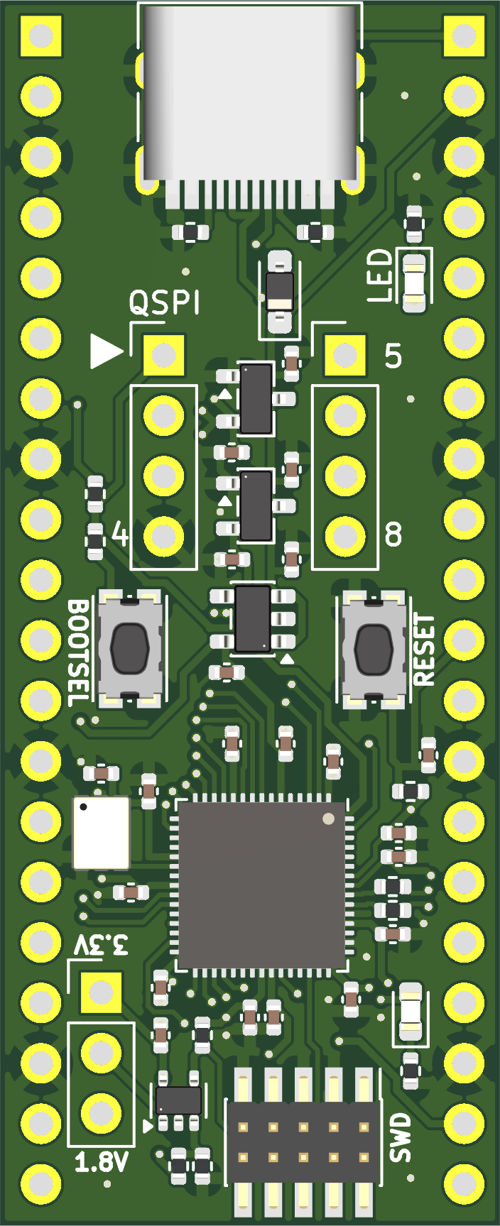
3V3(OUT) pin is actually the output of the selected voltage, so it is instead a VDD(OUT) pin, which is only powered when a jumper is fitted to the voltage selector header. Additionally, the 3V3_EN pin is left floating on Pico 2V.RESET button will tie the RUN pin to ground.SS (note that pressing the BOOTSEL button will tie this to ground, even after the bootrom exits -- this is a fundamental constraint of how the RP235x bootrom works).SD1/MISOSD2GNDVDD (voltage determined by voltage selection jumper)SD3SCLKSD0/MOSIFabrication exports are in the fab/rev0 directory. I had the board produced by JLCPCB. To have JLCPCB produce some boards for you to have, zip all the files in the fab/rev0 directory and provide the ZIP file to JLCPCB. I used Lead-Free HASL as the surface finish and a PCB thickness of 1mm. If you want them to assembly the components onto the board as well, provide them the BOM and CPL files in fab/rev0/smt/pico-2v-bom.xls and fab/rev0/smt/pico-2v-all-pos.csv respectively. Note that the GPIO and QSPI headers are not included in the BOM file, but the voltage selection header is; you can select or remove these as you desire.
| Qty | Value | Footprint | References |
|---|---|---|---|
| 13 | 100nF | Capacitor_SMD:C_0402_1005Metric | C2, C3, C4, C5, C6, C7, C8, C9, C10, C11, C12, C18, C20 |
| 6 | 1uF | Capacitor_SMD:C_0402_1005Metric | C13, C14, C15, C16, C17, C19 |
| 4 | 10k | Resistor_SMD:R_0402_1005Metric | R1, R6, R10, R11 |
| 2 | 1k | Resistor_SMD:R_0402_1005Metric | R2, R9 |
| 2 | 27 | Resistor_SMD:R_0402_1005Metric | R3, R4 |
| 2 | 470R | Resistor_SMD:R_0402_1005Metric | R5, R12 |
| 2 | 5.1K | Resistor_SMD:R_0402_1005Metric | R7, R8 |
| 2 | Conn_01x04 | Connector_PinHeader_2.54mm:PinHeader_1x04_P2.54mm_Vertical | J5, J6 |
| 2 | KMR231GLFS | Button_Switch_SMD:SW_Push_1P1T_NO_CK_KMR2 | SW1, SW2 |
| 2 | RED | LED_SMD:LED_0603_1608Metric | D2, D3 |
| 1 | 10uF | Capacitor_SMD:C_0402_1005Metric | C21 |
| 1 | 4.7uF | Capacitor_SMD:C_0402_1005Metric | C1 |
| 1 | BS5817WS | Diode_SMD:D_SOD-323_HandSoldering | D1 |
| 1 | Conn_02x05_Odd_Even | Connector_PinHeader_1.27mm:PinHeader_2x05_P1.27mm_Vertical_SMD | J7 |
| 1 | ECS-3225MV-120-BN-TR3 | pico-2v:ECS-3225MV-120-BN-TR3 | Y1 |
| 1 | Header-1 | Connector_PinHeader_2.54mm:PinHeader_1x20_P2.54mm_Vertical | J3 |
| 1 | Header-2 | Connector_PinHeader_2.54mm:PinHeader_1x20_P2.54mm_Vertical | J4 |
| 1 | LMV331 | Package_TO_SOT_SMD:SOT-353_SC-70-5 | U5 |
| 1 | MCP1703T-1802E/CB | Package_TO_SOT_SMD:SOT-23 | U3 |
| 1 | MCP1703T-3302E/CB | Package_TO_SOT_SMD:SOT-23 | U2 |
| 1 | RP2354A | pico-2v:RP2350A-QFN-60-1EP_7x7_P0.4mm_EP3.4x3.4mm_ThermalVias | U1 |
| 1 | TLV71311PDBVR | Package_TO_SOT_SMD:SOT-23-5 | U4 |
| 1 | USB_C_Receptacle_USB2.0_16P | pico-2v:USB_C_Receptacle_HRO_TYPE-C-31-M-12 | J1 |
| 1 | VOLTSEL | Connector_PinHeader_2.54mm:PinHeader_1x03_P2.54mm_Vertical | J2 |
The 51 most common of 53 parts.
It measures 51.5 × 21 mm and has 4 copper layers, 0.8 mm thick.
53 parts, built around the RP2354A, LMV331TP, WR04X4700FTL and WR04X5101FTL. The full list of its parts is on this page, with links to each part's symbol and footprint where PCBKit's library has them.
From the lucasbaizer/pico-2v repository on GitHub, at the commit this page was made from: the board is pico-2v.kicad_pcb and its schematic pico-2v.kicad_sch. PCBKit opens the board in the browser, with nothing to install.
Its repository states no licence, so its author keeps all rights: ask lucasbaizer before reusing the design.
CIRCUITSTATE/Mitayi-Pico-D1
Open-Source RP2040 Microcontroller Development Board

Smoothieware/Smoothieboard2
Hardware files for the Smoothieboard v2, and extension boards

CIRCUITSTATE/PBSEQ-D2
A simple push-button controlled power sequencer circuit demo board.


CDFER/NIMRS-21Pin-Decoder
An open source 21-Pin DCC Decoder for model trains

synfinatic/GoProControl
GoPro WiFi controller board using an ESP8266 allowing easy integration with other circuits

SkullKill/ESP32-Wall-Clock-PCB
ESP32 based 30cm Wall Mounted Clock. WiFi, NTP, SNMP, web interface, MicroUsb, Type-C, HG3613 Retrofit
