

2 layers287.8 × 126.7 mm

 CDFER/NIMRS-21Pin-Decoder21
An open source 21-Pin DCC Decoder for model trains
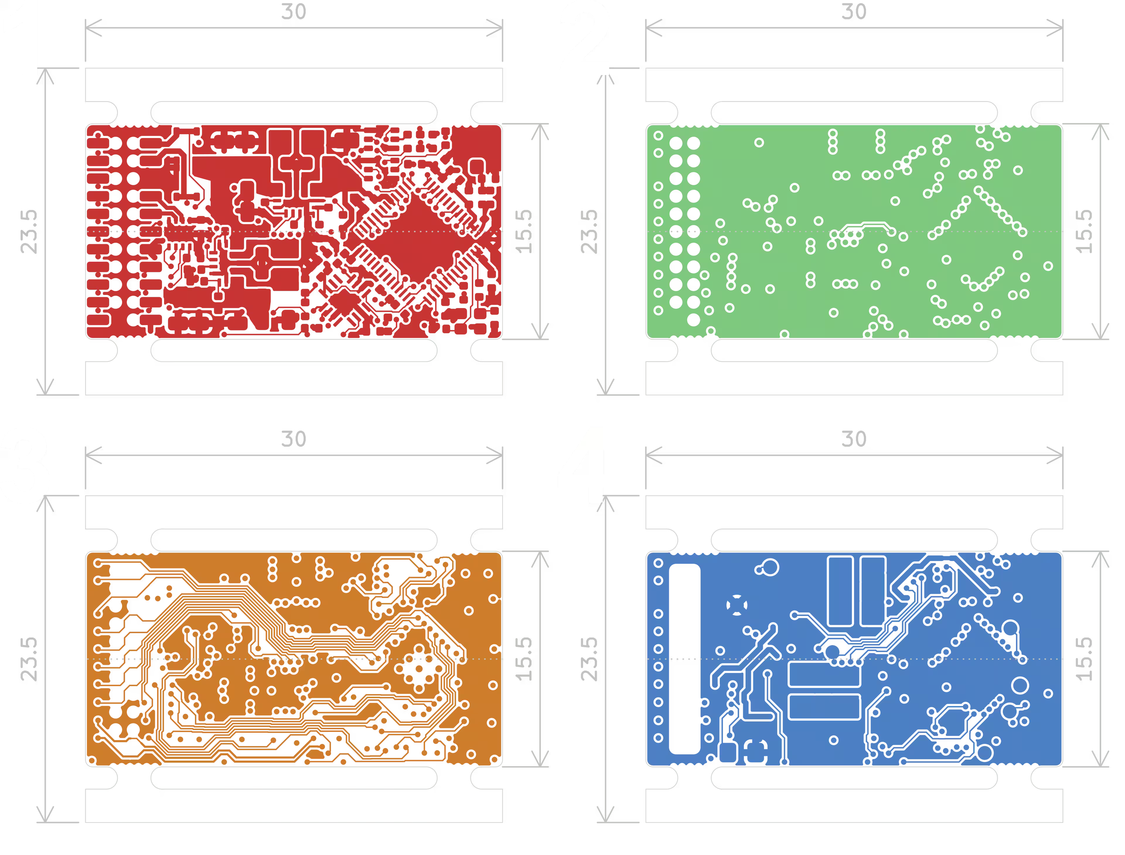
NIMRS-21Pin Decoder is an open-source printed circuit board by CDFER, from the CDFER/NIMRS-21Pin-Decoder repository on GitHub. It is a 4-layer board of 30 × 23.5 mm with 89 parts on 85 nets, routed with 1,360 tracks and 197 vias.
It is built around the ESP32-S3FN8, TPS63070RNM and B5817WS, with the MMDT3904 and BZX584C18 among its other parts. Its parts include 28 capacitors, 23 resistors, 5 ICs, 5 diodes and 4 inductors. It belongs with the ESP32 boards of this library.


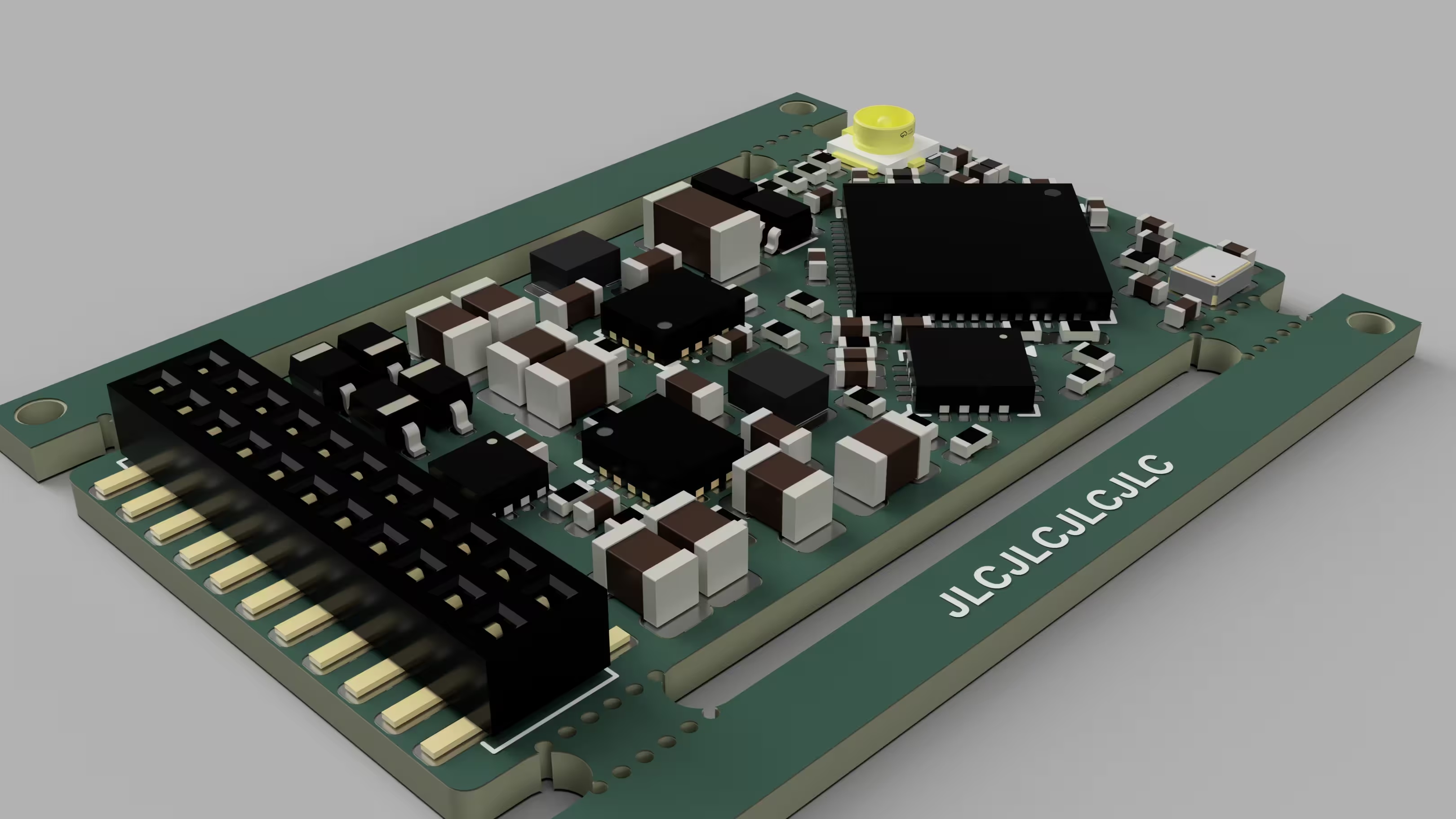
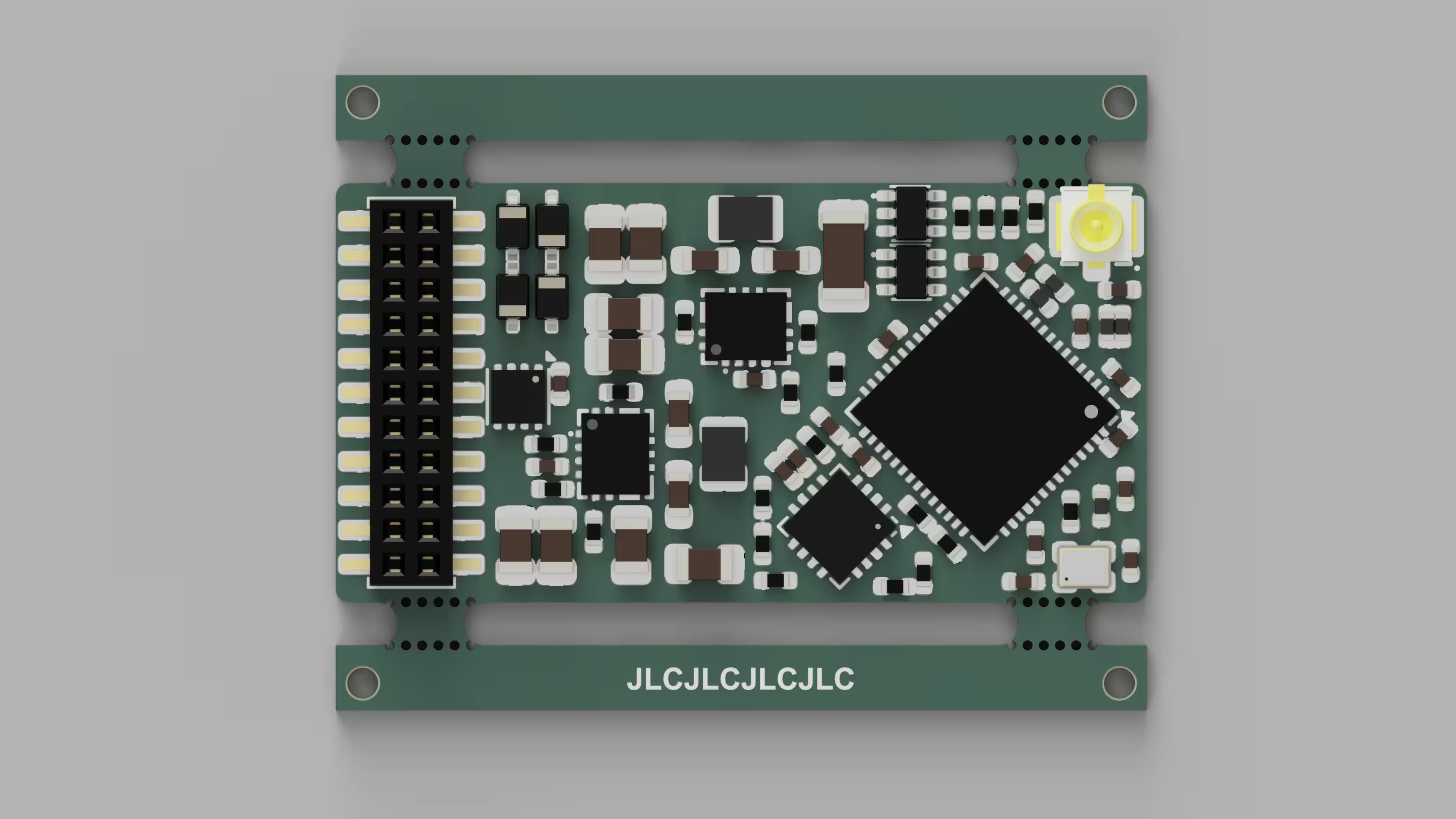
A miniature DCC decoder for model railways featuring an ESP32-S3 microcontroller, designed to fit standard 21-pin sockets. Includes motor control, sound output, and lighting control in a 30x15.5mm footprint (following NMRA spec).
I don't quite have the time to work on this project at the momemnt but Kyle (ProjectInitiative) is starting to work on firmware for this board. You can follow the progress here: https://github.com/ProjectInitiative/NIMRS-Firmware
Clone the repository:
git clone https://github.com/CDFER/NIMRS-21Pin-Decoder.gitOpen in KiCad v9.0+
Review design files:
├── Custom_Footprints.pretty  # Custom component footprints
├── Datasheets               # Component technical documents
├── Images                   # PCB visuals and renders
├── LICENSE
└── README.md
For those wondering the 21-Pin decoder socket uses a 1.27mm, 22Pin back entry connector and I am using the BD050-22-A-0-0500-L-D from GCT (the CAD file, footprint and symbol can be found in the custom footprints library I have made).
MIT License - See LICENSE for details.
Pull requests welcome! Please discuss major changes via issues first.
| Qty | Value | Footprint | References |
|---|---|---|---|
| 10 | Test Point | Custom_Footprints:TestPoint_Pad_D1.0mm | TP1, TP2, TP3, TP4, TP5, TP6, TP7, TP8, TP9, TP10 |
| 8 | 10uF | PCM_JLCPCB:C_0402 | C1, C2, C7, C9, C11, C15, C16, C75 |
| 8 | 22uF | PCM_JLCPCB:C_0805 | C60, C61, C64, C65, C66, C67, C70, C71 |
| 4 | 10uF | PCM_JLCPCB:C_0603 | C62, C63, C72, C73 |
| 4 | 1kΩ | PCM_JLCPCB:R_0402 | R12, R13, R14, R15 |
| 4 | 75kΩ | PCM_JLCPCB:R_0402 | R4, R6, R8, R71 |
| 4 | B5817WS | Custom_Footprints:D_SOD-323 | D1, D2, D3, D4 |
| 4 | ~ | PCM_JLCPCB:Hole_Tooling_JLCPCB | H1, H2, H3, H4 |
| 3 | 20kΩ | PCM_JLCPCB:R_0402 | R5, R7, R9 |
| 2 | 1.0uH,4.1A | Custom_Footprints:IND-SMD_L2.0-W1.6-B | L60, L70 |
| 2 | 1.5pF | PCM_JLCPCB:C_0402 | C12, C13 |
| 2 | 100kΩ | PCM_JLCPCB:R_0402 | R63, R73 |
| 2 | 100nF | PCM_JLCPCB:C_0402 | C68, C76 |
| 2 | 10kΩ | PCM_JLCPCB:R_0402 | R60, R70 |
| 2 | 20pF | PCM_JLCPCB:C_0402 | C8, C10 |
| 2 | 510kΩ | PCM_JLCPCB:R_0402 | R3, R61 |
| 2 | MMDT3904 | Custom_Footprints:SOT-363_SC-70-6 | Q1, Q2 |
| 2 | R | Resistor_SMD:R_0805_2012Metric_Pad1.20x1.40mm_HandSolder | R2, R11 |
| 2 | TPS63070 | Custom_Footprints:RNM0015A | U60, U70 |
| 1 | 100uF | PCM_JLCPCB:C_1206 | C74 |
| 1 | 15nH,300mA | PCM_JLCPCB:L_0402 | L3 |
| 1 | 1uF | PCM_JLCPCB:C_0402 | C17 |
| 1 | 2.4kΩ | PCM_JLCPCB:R_0402 | R10 |
| 1 | 2.7nH | PCM_JLCPCB:L_0402 | L1 |
| 1 | 21Pin Loco Socket | Custom_Footprints:BD050-22-A-0-0500-L-D | J1 |
| 1 | 24kΩ | PCM_JLCPCB:R_0402 | R72 |
| 1 | 40Mhz | Custom_Footprints:Crystal_SMD_2016-4Pin_2.0x1.6mm | X1 |
| 1 | 470Ω | PCM_JLCPCB:R_0402 | R1 |
| 1 | 51kΩ | PCM_JLCPCB:R_0402 | R62 |
| 1 | BZX584C18 | Custom_Footprints:D_SOD-523 | D5 |
| 1 | DRV8213DSGR | Custom_Footprints:WSON-8-1EP_2x2mm_P0.5mm_EP0.9x1.6mm | U4 |
| 1 | ESP32-S3FN8 | Custom_Footprints:QFN-56-1EP_7x7mm_P0.4mm_EP4x4mm_ThermalVias | U1 |
| 1 | MAX98357A | Custom_Footprints:TQFN-16-1EP_3x3mm_P0.5mm_EP1.23x1.23mm | U2 |
| 1 | U.FL | Custom_Footprints:IPEX-SMD_BWIPX-1-001E | J2 |
| 1 | ~ | PCM_JLCPCB:Part_Num_JLCPCB | PN1 |
The 85 most common of 89 parts.
It measures 30 × 23.5 mm and has 4 copper layers, 1.04 mm thick.
89 parts, built around the ESP32-S3FN8, TPS63070RNM, B5817WS and MMDT3904. The full list of its parts is on this page, with links to each part's symbol and footprint where PCBKit's library has them.
From the CDFER/NIMRS-21Pin-Decoder repository on GitHub, at the commit this page was made from: the board is Decoder PCB/NIMRS-21Pin-Decoder.kicad_pcb and its schematic Debug PCB/Debug PCB.kicad_sch. PCBKit opens the board in the browser, with nothing to install.
Its repository states no licence, so its author keeps all rights: ask CDFER before reusing the design.

Smoothieware/Smoothieboard2
Hardware files for the Smoothieboard v2, and extension boards

CIRCUITSTATE/Mitayi-Pico-D1
Open-Source RP2040 Microcontroller Development Board

synfinatic/GoProControl
GoPro WiFi controller board using an ESP8266 allowing easy integration with other circuits


JordanAceto/CEM3340_VCO
PCB for a CEM3340 based VCO with sine, triangle, saw, and pulse waves.

SkullKill/ESP32-Wall-Clock-PCB
ESP32 based 30cm Wall Mounted Clock. WiFi, NTP, SNMP, web interface, MicroUsb, Type-C, HG3613 Retrofit

Andreuxxx1977/esp32-p4
An open-hardware, actively cooled ESP32-P4 board for heavy multimedia work: a 2-lane MIPI camera, a 2-lane MIPI display, USB 2.0 High-Speed, 10/100 Ethernet, UHS-I microSD, 32 MB flash and 32 MB PSRAM.