2 layers205.5 × 64.2 mm

 lprib/sbc3
single board computer thingy
Sbc3 pcb is an open-source printed circuit board by lprib, from the lprib/sbc3 repository on GitHub. It is a 2-layer board of 120 × 93 mm with 181 parts on 164 nets, routed with 1,586 tracks and 226 vias.
It is built around the STM32F405VGT6, SP3485EN-L/TR and 74HC595D,118, with the PJ-342 among its other parts. Its parts include 65 resistors, 50 capacitors, 18 diodes, 11 connectors and 10 ICs. It belongs with the computers and single-board computers boards and the STM32 boards of this library.


Self contained board that can be easily programmed on target for fun little games or GUIs. Inspired by the environment presented by TI calculators and TI-BASIC.
sbc3
|_ art: various images for putting on PCB and for on-screen graphics
|_ cubemx: STM32 CubeMX projects for pinmapping
|_ docs: datasheets etc
|  |_ cpu_hardware: hardware support and layout for STM32s
|  |_ hardware: various datasheets for parts used
|  \_ sofware: CPU ref manuals etc
|_ img: images for docs
|_ keyboard_v1: kicad project for keyboard
|_ main_board_v1: kicad project for main board
|_ rust_firmware: Firmware and screen driver in Rust (abandoned for now)
\_ software: (mostly c++) software and firmware
   |_ cmake: cmake scripts
   |_ firmware: firmware for main_board_v1
   |  |_ app: main application sources
   |  \_ (other dirs): supporting libraries unchanged from CubeMX/FreeRTOS upstream
   \_ vm: virtual machine
      |_ analysis: jupyter notebook for vm stat calculations
      |_ engine: main vm sources (portable)
      |_ pc_port: raylib port of VM for desktop
      |_ programs: sbc3 assembly programs
      |_ tests: vm unit tests (lol)
      |_ vscode-extension-sbcs-syntax: syntax support in VSCode for SBC3 assembly
      \_ as2.py: sbc3 vm bytecode assembler
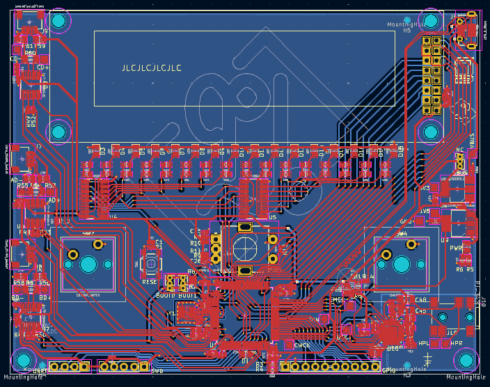
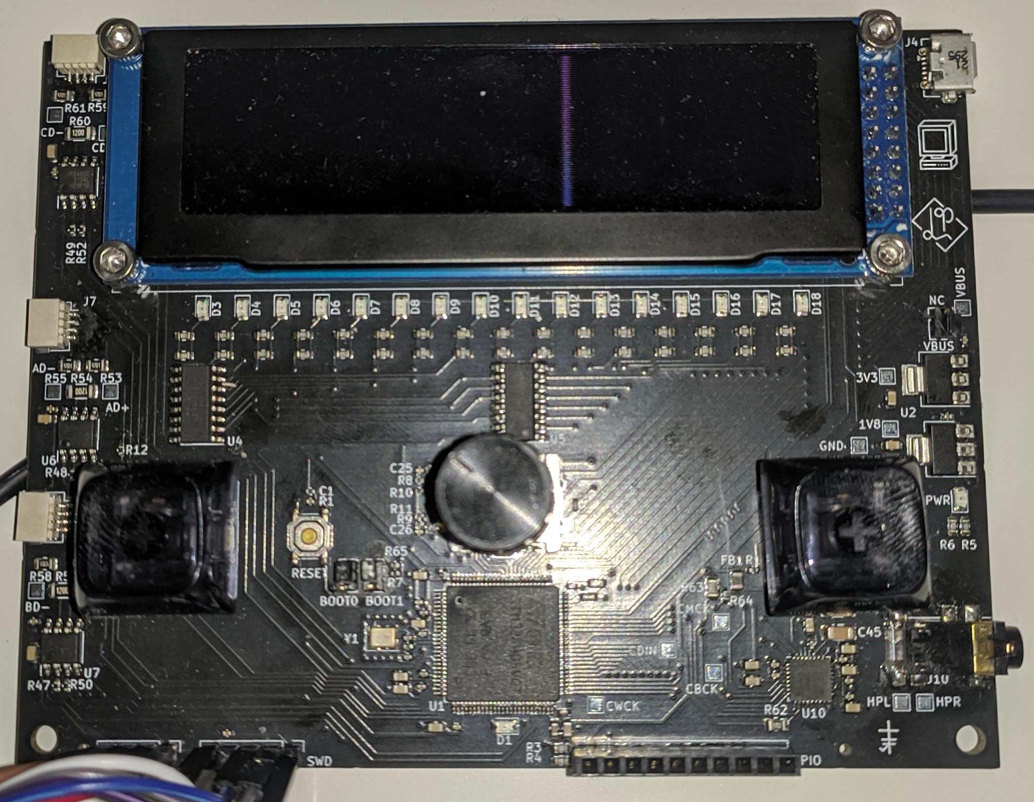

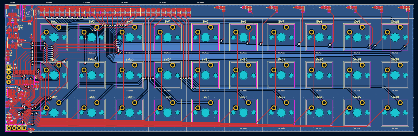
Not yet manufactured, since still thinking about re-doing the comms (definitely not going to use the current JST connectors as theyre much too finicky).
Also included is a stack based virtual bytecode machine (see software/vm). The bytecode can call out to pre-defined system modules, including graphics routines. Below is an example of the main board STM32 and a Linux desktop running the same bytecode program.
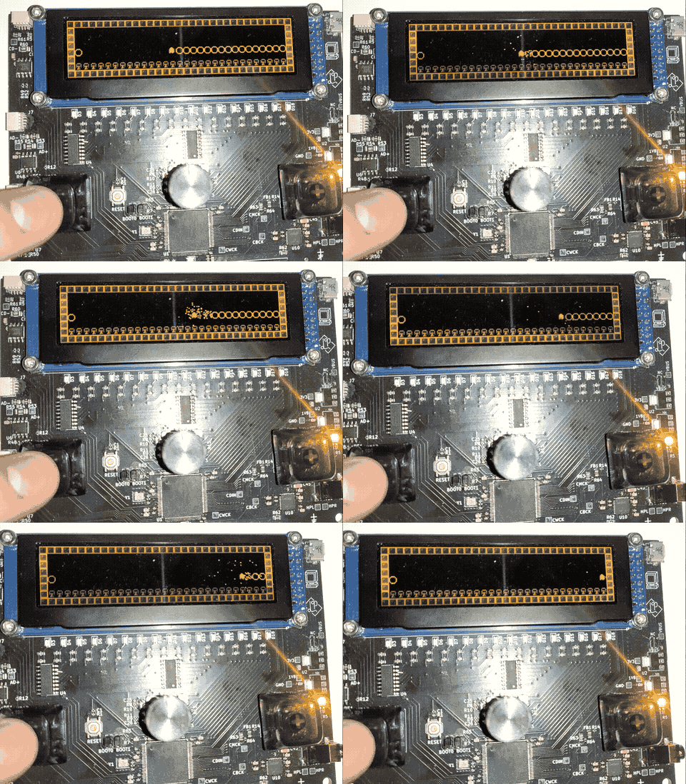
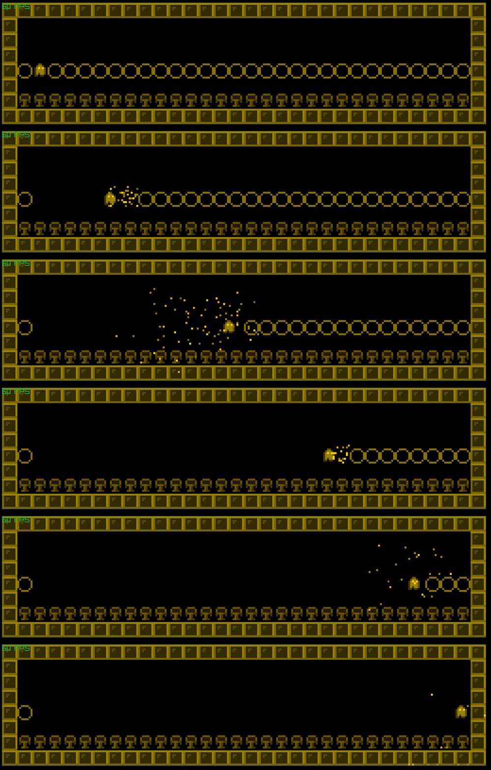
As the bytecode is stack based, a thin forth layer has been built for it, which is currently assembled by a python script. See the source program for the above gifs here.
| Qty | Value | Footprint | References |
|---|---|---|---|
| 36 | 150 | Resistor_SMD:R_0603_1608Metric | R3, R15, R16, R17, R18, R19, R20, R21, R22, R23, R24, R25, R26, R27, R28, R29 +20 |
| 22 | 100n | Capacitor_SMD:C_0402_1005Metric | C1, C11, C12, C14, C17, C18, C20, C22, C24, C28, C29, C31, C33, C35, C40, C42 +6 |
| 19 | 10u | Capacitor_SMD:C_0603_1608Metric | C10, C13, C15, C16, C19, C21, C23, C27, C30, C32, C34, C36, C39, C41, C43, C46 +3 |
| 17 | 10k | Resistor_SMD:R_0402_1005Metric | R1, R7, R8, R10, R11, R12, R13, R14, R47, R48, R49, R50, R51, R52, R64, R65 +1 |
| 16 | LED | LED_SMD:LED_0805_2012Metric | D3, D4, D5, D6, D7, D8, D9, D10, D11, D12, D13, D14, D15, D16, D17, D18 |
| 8 | 4k7 | Resistor_SMD:R_0805_2012Metric | R53, R55, R56, R58, R59, R61, R62, R63 |
| 3 | 120 | Resistor_SMD:R_1206_3216Metric | R54, R57, R60 |
| 3 | Conn_01x04_Socket | Connector_JST:JST_SH_SM04B-SRSS-TB_1x04-1MP_P1.00mm_Horizontal | J7, J8, J9 |
| 3 | MountingHole | sbc:MountingHole_JLCPCB_Assembly | H3, H4, H5 |
| 3 | SP3485EN-L/TR | Package_SO:SOIC-8_3.9x4.9mm_P1.27mm | U6, U7, U8 |
| 2 | 10n | Capacitor_SMD:C_0402_1005Metric | C25, C26 |
| 2 | 10p | Capacitor_SMD:C_0402_1005Metric | C2, C3 |
| 2 | 2.2u | Capacitor_SMD:C_0603_1608Metric | C4, C5 |
| 2 | 47u | Capacitor_SMD:C_1206_3216Metric | C45, C48 |
| 2 | 74HC595D,118 | Package_SO:SOIC-16_3.9x9.9mm_P1.27mm | U4, U5 |
| 2 | CHERRY_SWITCH | Button_Switch_Keyboard:SW_Cherry_MX_1.00u_PCB | SW2, SW4 |
| 2 | MountingHole | MountingHole:MountingHole_3.2mm_M3 | H1, H2 |
| 1 | 16MHz | Crystal:Crystal_SMD_3225-4Pin_3.2x2.5mm | Y1 |
| 1 | 1V8 | sbc:MyTP | TP10 |
| 1 | 1k | Resistor_SMD:R_0402_1005Metric | R2 |
| 1 | 1u | Capacitor_SMD:C_0402_1005Metric | C7 |
| 1 | 256x64 SSD1322 Module | sbc:SSD1322_oled_module_3.12inch | U3 |
| 1 | 3V3 | sbc:MyTP | TP1 |
| 1 | AD+ | sbc:MyTP | TP4 |
| 1 | AD- | sbc:MyTP | TP5 |
| 1 | BD+ | sbc:MyTP | TP6 |
| 1 | BD- | sbc:MyTP | TP7 |
| 1 | BOOT0 | Connector_PinHeader_1.27mm:PinHeader_1x03_P1.27mm_Vertical | J2 |
| 1 | BOOT1 | Connector_PinHeader_1.27mm:PinHeader_1x03_P1.27mm_Vertical | J11 |
| 1 | CBCK | sbc:MyTP | TP13 |
| 1 | CD+ | sbc:MyTP | TP8 |
| 1 | CD- | sbc:MyTP | TP9 |
| 1 | CDIN | sbc:MyTP | TP12 |
| 1 | CMCK | sbc:MyTP | TP11 |
| 1 | CWCK | sbc:MyTP | TP14 |
| 1 | DBG | LED_SMD:LED_0805_2012Metric | D1 |
| 1 | FerriteBead | Inductor_SMD:L_0805_2012Metric | FB1 |
| 1 | GND | sbc:MyTP | TP17 |
| 1 | GPIO | Connector_PinSocket_2.54mm:PinSocket_1x10_P2.54mm_Vertical | J3 |
| 1 | HPL | sbc:MyTP | TP16 |
| 1 | HPR | sbc:MyTP | TP15 |
| 1 | LD1117S18TR_SOT223 | Package_TO_SOT_SMD:SOT-223-3_TabPin2 | U9 |
| 1 | LD1117S33TR_SOT223 | Package_TO_SOT_SMD:SOT-223-3_TabPin2 | U2 |
| 1 | PJ-342 | sbc:PJ-342 | J10 |
| 1 | PWR | LED_SMD:LED_0805_2012Metric | D2 |
| 1 | RESET | Button_Switch_SMD:SW_Push_1P1T_XKB_TS-1187A | SW1 |
| 1 | RotaryEncoder_Switch | Rotary_Encoder:RotaryEncoder_Alps_EC11E-Switch_Vertical_H20mm | SW3 |
| 1 | STM32F405VGT6 | Package_QFP:LQFP-100_14x14mm_P0.5mm | U1 |
| 1 | SWD | Connector_PinHeader_2.54mm:PinHeader_1x05_P2.54mm_Vertical | J6 |
| 1 | TLV320DAC3101IRHBR | Package_DFN_QFN:VQFN-32-1EP_5x5mm_P0.5mm_EP3.15x3.15mm | U10 |
| 1 | UART | Connector_PinHeader_2.54mm:PinHeader_1x04_P2.54mm_Vertical | J5 |
| 1 | USB_B_Micro | Connector_USB:USB_Micro-AB_Molex_47590-0001 | J4 |
| 1 | VBUS | sbc:MyTP | TP3 |
| 1 | VBUS CON | Connector_PinHeader_1.27mm:PinHeader_1x03_P1.27mm_Vertical | J1 |
It measures 120 × 93 mm and has 2 copper layers, 1.6 mm thick.
181 parts, built around the STM32F405VGT6, SP3485EN-L/TR, 74HC595D,118 and PJ-342. The full list of its parts is on this page, with links to each part's symbol and footprint where PCBKit's library has them.
From the lprib/sbc3 repository on GitHub, at the commit this page was made from: the board is main_board_v1/sbc3_pcb.kicad_pcb and its schematic keyboard_v1/keyboard.kicad_sch. PCBKit opens the board in the browser, with nothing to install.
Its repository states no licence, so its author keeps all rights: ask lprib before reusing the design.

KOEGlike/meko
A linux music player with ddr3, a 70hz e-paper display and a haptic touchpad

RADARC/Scout-Radio
Si4732 and Raspberry Pi Pico Radio device for Scouts to build and use to gain badges


mojo626/iPodClone
This is a clone of an iPod video based on the Allwinner V3s processor


freakontrol/stmbl
THE AUTHORS OF THIS SOFTWARE ACCEPT ABSOLUTELY NO LIABILITY FOR ANY HARM OR LOSS RESULTING FROM ITS USE. IT IS EXTREMELY UNWISE TO RELY ON SOFTWARE ALONE FOR SAFETY.
