
2 layers29.8 × 49.8 mm

This project is, first and foremost, a custom devboard made for macondo. It has a esp32-c3 chip on it. A main tenant of its design is to be as power efficient as possible, because of its secondary purpose as a GNSS…
Gps is an open-source printed circuit board by louis-bourgault, from the louis-bourgault/gps repository on GitHub. It is a 2-layer board of 24 × 40 mm with 26 parts on 31 nets, routed with 240 tracks and 29 vias.
It is built around the ESP32-C3-WROOM-02-H4, TP4057 and TPS78330DDCR, with the SS14 among its other parts. Its parts include 6 resistors, 5 capacitors, 5 connectors, 4 diodes and 3 ICs. It belongs with the radio and wireless boards and the ESP32 and RISC-V boards of this library.


This project is, first and foremost, a custom devboard made for macondo. It has a esp32-c3 chip on it. A main tenant of its design is to be as power efficient as possible, because of its secondary purpose as a GNSS board. GNSS is not the primary use - the primary use is to have a functional, simple, and useful devboard for my own purpose. However, it is a likely extention of the project. The idea is that I've put a bunch of pins on the PCB in the right place to connect to a GNSS module, specifically the ATGM336 family, and designed something power efficient enough to run intermittent tracking for up to, ideally, 10 days or so while using a 1000mAh battery. Macondo reviewers: if i end up doing the GNSS thing, i will buy the chip myself (it's cheap) later on
The device uses the esp32-c3-mini-n4, which is a module which contains 4mb of inbuilt flash storage. You can program it through the ESP-IDF in C or C#, or through the Arduino IDE.
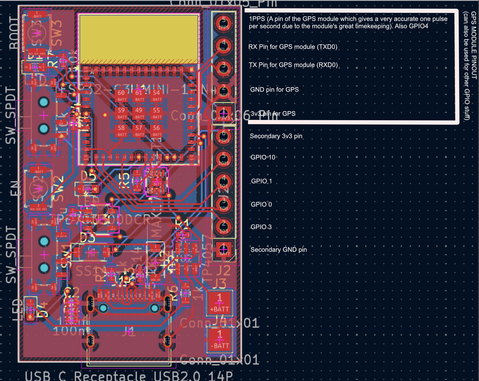 The GNSS pins are the top 5, although of course they can be used for other things, GNSS is just the reason they are arranged in this way.
Prod files can be found at /hardware/jlcpcb/production-files.
| Qty | Value | Footprint | References |
|---|---|---|---|
| 2 | 100nf | Capacitor_SMD:C_0402_1005Metric | C4, C5 |
| 2 | 10k | Resistor_SMD:R_0402_1005Metric | R4, R8 |
| 2 | 1u | Capacitor_SMD:C_0402_1005Metric | C1, C2 |
| 2 | 5.1k | Resistor_SMD:R_0402_1005Metric | R2, R3 |
| 2 | Conn_01x01 | TestPoint:TestPoint_Pad_2.5x2.5mm | J3, J4 |
| 2 | LED | LED_SMD:LED_0603_1608Metric | D4, D5 |
| 2 | SS14 | Diode_SMD:D_SOD-123 | D2, D3 |
| 2 | SW_SPDT | Button_Switch_SMD:SW_SPDT_Shouhan_MSK12C02 | SW1, SW4 |
| 1 | 10uf | Capacitor_SMD:C_0402_1005Metric | C3 |
| 1 | 1k | Resistor_SMD:R_0603_1608Metric | R6 |
| 1 | 2k | Resistor_SMD:R_0402_1005Metric | R1 |
| 1 | BOOT | Button_Switch_SMD:SW_Push_SPST_NO_Alps_SKRK | SW5 |
| 1 | Conn_01x05_Pin | Connector_PinHeader_2.54mm:PinHeader_1x05_P2.54mm_Vertical | J5 |
| 1 | Conn_01x06_Pin | Connector_PinHeader_2.54mm:PinHeader_1x06_P2.54mm_Vertical | J2 |
| 1 | ESP32-C3-WROOM-02 | RF_Module:ESP32-C3-WROOM-02 | U5 |
| 1 | TP4057 | Package_TO_SOT_SMD:SOT-23-6 | U2 |
| 1 | TPS78330DDCR | Custom:DDC5_TEX | U3 |
| 1 | USB_C_Receptacle_USB2.0_14P | Connector_USB:USB_C_Receptacle_HRO_TYPE-C-31-M-12 | J1 |

RunningJoke/reactionButton
ReactPod: ESP32-C3 reaction buzzers – firmware, Config App (PWA), tools, hardware


Aust1nke/Security_shop_guard
I built this pcb using esp32, and lidar sensor to monitor and alert shop owner of intruders

bardiasayyar/Custom-PCB-Wearable-Step-Fall-Tracker
Designing a custom wristband PCB in KiCad integrating an ESP32-C3 microcontroller, LSM6DS3 IMU (I2C), and LiPo battery/charging circuitry for real-time step counting, fall detection, and battery monitoring.


It measures 24 × 40 mm and has 2 copper layers, 1.6 mm thick.
26 parts, built around the ESP32-C3-WROOM-02-H4, TP4057, TPS78330DDCR and SS14. The full list of its parts is on this page, with links to each part's symbol and footprint where PCBKit's library has them.
From the louis-bourgault/gps repository on GitHub, at the commit this page was made from: the board is hardware/gps.kicad_pcb and its schematic hardware/gps.kicad_sch. PCBKit opens the board in the browser, with nothing to install.
Its repository states no licence, so its author keeps all rights: ask louis-bourgault before reusing the design.