2 layers48.9 × 55.2 mm
VedgaZigBee
vedga/pcb-RF-BM-2652
RFStar ZigBee modules development board PCB (designed by Vedga)
11 partsGPL-2.0

 lorenz/fanbee6
A Zigbee-controlled 140mm fan with electronically-controlled valve
Fanbee is an open-source printed circuit board by lorenz, from the lorenz/fanbee repository on GitHub, published under the MIT licence. It is a 2-layer board of 60.5 × 44 mm with 59 parts on 56 nets, routed with 305 tracks and 63 vias.
It is built around the 74HCT244D, RF-BM-2652P2 and TPS5430DDA, with the AO3401A, B5819W and MMBT3904 among its other parts. Its parts include 16 resistors, 14 capacitors, 5 ICs, 5 diodes and 3 connectors.


A Zigbee-controlled 140mm fan with electronically-controlled valve
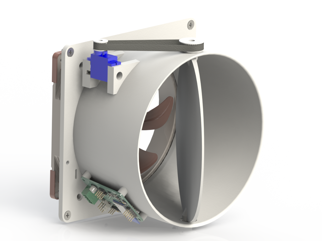
Skip to the Build Guide if you want to know how to build one.
The small LED (D3) near the reset button indicates if the lowest (MCU) power rail has power. If it is not illuminated nothing will happen, check power rails.
The firmware initially starts blinking its status LED (D4, near the JTAG header) every 2 seconds, indicating that it is idle and is not connected to any network. Press the Pair button after your ZigBee network is ready to join a new device. The status LED will start to blink rapidly (every 0.5s) until it has joined a network, then it will turn off.
Pressing the pair button while the device is already joined to a network will result in two quick flashes of the status LED.
Long-pressing the pair button (>5s) will reset the device.
The last LED (D5) indicates if the fan is currently powered. It can be used to diagnose fan or connectivity issues.
Because the ZigBee HVAC fan device type is unfit for this device (it supports various modes but no speed control) I've opted to implement it as a generic level-controlled device (just like dimmable lights). This should give it fairly broad coordinator compatibility.
There's a device model for the FanBee in Zigbee2MQTT which is what I'm personally using to control them.
| Quantity | Part description |
|---|---|
| 8 | M3 brass heat-set inserts |
| 1 | M3 15mm buttonhead fastener |
| 1 | M3 10mm buttonhead fastener |
| 4 | M3 5mm fastener (ideally with integrated washer) |
| 4 | M4 countersunk fasteners for attaching the housing |
| 2 | 10x15x4mm ball bearings |
| 1 | SG90-compatible 180° servo |
| 1 | 140mm 24V or 12V PC-compatible PWM fan (plus screws if not included) |
| 30cm | 2GT timing belt (open-loop) |
This was designed for the Noctua NF-A14 industrialPPC-24V-3000 SP IP67 PWM, but any other electrically-compatible 24V or 12V fans can be used. Note that the power supply voltage needs to match the fan voltage, there is no regulator for the fan power supply.
The control PCB is custom-designed and can be ordered at your favorite PCB manufacturer in various states of assembly. All SMT parts can be assembled for relatively cheap by JLCPCB. One PCB is needed for each FanBee.
A OpenOCD and JTAG compatible programmer with a 2.45mm ARM 10 Pin JTAG connector is required. This has been tested with a generic FT2232 board, but a TI XDS110 or compatible LaunchPad should also work.
The STLs for all printed parts are in the parts folder. One of each is
needed for a single fanbee.
servo_pulley.stl should be printed in resin or with a 0.2mm nozzle, the
rest of the parts do not need to be as precise.
MIT for all the code I wrote as well as the CAD design files. Some code is also related to TI's SimpleLink SDK (especially the generated syscfg), I don't claim ownership of that, but TI grants you relatively broad permissions for most use.
| Qty | Value | Footprint | References |
|---|---|---|---|
| 7 | 10k | Resistor_SMD:R_0402_1005Metric | R1, R3, R6, R9, R11, R13, R14 |
| 4 | 10u | Capacitor_SMD:C_0805_2012Metric | C1, C4, C7, C9 |
| 4 | MountingHole | MountingHole:MountingHole_3.2mm_M3 | H1, H2, H3, H4 |
| 4 | TestPoint | TestPoint:TestPoint_Pad_D1.0mm | TP1, TP2, TP3, TP4 |
| 3 | 0.1u | Capacitor_SMD:C_0402_1005Metric | C6, C11, C13 |
| 3 | 4.7k | Resistor_SMD:R_0402_1005Metric | R5, R15, R18 |
| 2 | 100n | Capacitor_SMD:C_0603_1608Metric | C12, C14 |
| 2 | 1u | Capacitor_SMD:C_0805_2012Metric | C5, C8 |
| 2 | Motor_Servo | Connector_PinHeader_2.54mm:PinHeader_1x03_P2.54mm_Vertical | M1, M2 |
| 1 | 10n | Capacitor_SMD:C_0402_1005Metric | C2 |
| 1 | 15k | Resistor_SMD:R_0402_1005Metric | R12 |
| 1 | 15u @ 6.5A | custom_footprints:L_Sunlord_MWSA1004_11.5x10.5mm | L1 |
| 1 | 170u | Capacitor_SMD:CP_Elec_6.3x5.9 | C3 |
| 1 | 1k | Resistor_SMD:R_0402_1005Metric | R10 |
| 1 | 2.2k | Resistor_SMD:R_0402_1005Metric | R4 |
| 1 | 2.7k | Resistor_SMD:R_0603_1608Metric | R7 |
| 1 | 3.24k | Resistor_SMD:R_0402_1005Metric | R2 |
| 1 | 33n | Capacitor_SMD:C_0603_1608Metric | C10 |
| 1 | 3V3OK | LED_SMD:LED_0805_2012Metric | D3 |
| 1 | 5A | Diode_SMD:D_SMA | D1 |
| 1 | 74HCT244 | Package_SO:TSSOP-20_4.4x6.5mm_P0.65mm | U4 |
| 1 | 8.2k | Resistor_SMD:R_0402_1005Metric | R8 |
| 1 | ACT | LED_SMD:LED_0805_2012Metric | D4 |
| 1 | AO3401A | Package_TO_SOT_SMD:SOT-23 | Q2 |
| 1 | B5819W | Diode_SMD:D_SOD-123 | D2 |
| 1 | FAN | Connector:FanPinHeader_1x04_P2.54mm_Vertical | M3 |
| 1 | FAN_EN | LED_SMD:LED_0805_2012Metric | D5 |
| 1 | JTAG | Connector_PinHeader_2.54mm:PinHeader_2x05_P2.54mm_Vertical | J3 |
| 1 | MMBT3904 | Package_TO_SOT_SMD:SOT-23 | Q3 |
| 1 | PAIR | Button_Switch_SMD:SW_SPST_TL3342 | SW1 |
| 1 | PWR | Connector_Phoenix_MC:PhoenixContact_MCV_1,5_4-G-3.81_1x04_P3.81mm_Vertical | J1 |
| 1 | RESET | Button_Switch_SMD:SW_SPST_TL3342 | SW2 |
| 1 | RF-BM-2652P2 | custom_footprints:RF-BM-2652P2 | U5 |
| 1 | TPS5430DDA | Package_SO:TI_SO-PowerPAD-8_ThermalVias | U1 |
| 1 | UART | Connector_PinHeader_2.54mm:PinHeader_1x03_P2.54mm_Vertical | J7 |
| 1 | XC6206PxxxMR | Package_TO_SOT_SMD:SOT-23-3 | U3 |
| 1 | ~ | custom_footprints:Macronix_USON8_EP_2x3_Pitch0.5mm | U2 |
It measures 60.5 × 44 mm and has 2 copper layers, 1.6 mm thick.
59 parts, built around the 74HCT244D, RF-BM-2652P2, TPS5430DDA and AO3401A. The full list of its parts is on this page, with links to each part's symbol and footprint where PCBKit's library has them.
From the lorenz/fanbee repository on GitHub, at the commit this page was made from: the board is pcb/fanbee.kicad_pcb and its schematic pcb/fanbee.kicad_sch. PCBKit opens the board in the browser, with nothing to install.
Its repository publishes it under the MIT licence: you may reuse it on that licence's terms (keep the author's notice, and for a copyleft licence share your changes alike).
vedga/pcb-RF-BM-2652
RFStar ZigBee modules development board PCB (designed by Vedga)

pms67/BananaSchplit
Single rail DC (<12V) to split rail DC supply (+/-12V and +5V).


hallo-alex/SqueezeAMPagain
As github annoys me with their 2FA policy I'm moving this to codeberg

kingMordred/single_to_split_rail_dc_power_supply
PCB design using KiCad 10.0 for a single to split rail dc power supply, converting an input of +6V ~ +12V to a +5V rail or a +12V/-12V rail.


Uttu2611/DC---DC-Buck-Converter-
DC - DC Buck Converter schematic and PCB files for drop the DC Voltage levels.

TobleMiner/DC-UPS
A small DC UPS, designed to keep small appliances like consumer network equipment running during power outages