4 layers82.5 × 65.5 mm

 TobleMiner/DC-UPS223
A small DC UPS, designed to keep small appliances like consumer network equipment running during power outages
Dc usv is an open-source printed circuit board by TobleMiner, from the TobleMiner/DC-UPS repository on GitHub, published under the CERN-OHL-P-2.0 licence. It is a 4-layer board of 140 × 100 mm with 351 parts on 244 nets, routed with 2,597 tracks and 808 vias.
It is built around the 74HC595, AO4407A and MMBT3904, with the AON7544, P6SMB18CA and 1N4148WS among its other parts. Its parts include 134 resistors, 105 capacitors, 37 transistors, 21 diodes and 9 ICs. It belongs with the power boards of this library.


This repository contains the design files for a DC uninterruptible power supply well suited to run network appliances like small switches, home routes and WLAN access points.
I would not recommend ordering RevC yet as it is still untested.
I would not recommend ordering RevB yet as there are still some issues with the current design.
See Rev B issues below.
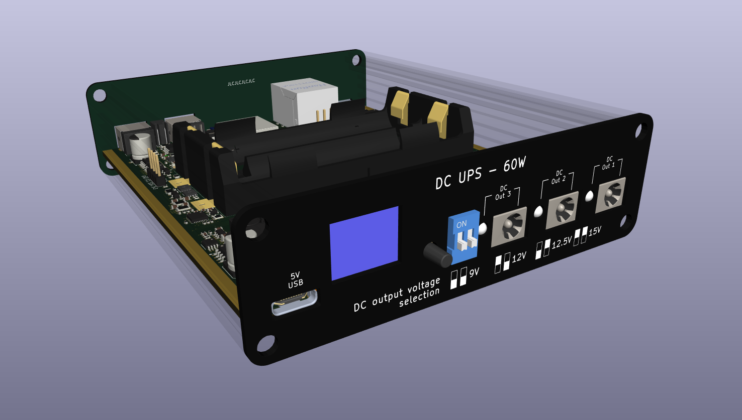
The mechanical construction of the DC UPS is based on 4 assemblies:
The three PCBs have been optimized for manufacturing through JLCPCB.
The main PCB is also designed to be suitable for assembly through JLCPCB.
The relevant fabrication files are located in fab.
For final assembly it is recommended to countersink the screw holes in front and rear panel. This will allow the screws included with the case to sit flush.
When using the JLCPCB assembly service only a very limited number of components needs to be assembled by hand:
For better thermal management I would highly recommend to install a thick, generously sized thermal pad below U4 and L2 contacting the bottom case if using the UPS DC outputs beyond 40W output power.
The DC UPS is running Open Source firmware. Firmware source can be found on GitHub here: https://github.com/TobleMiner/dc-ups-firmware
For a long time I was running the core of my home network (a cable modem,
router and switch) off a normal line-interactive AC UPS.
This was never ideal for a number of reasons. First of all the UPS was
using sealed lead acid batterys. The UPS did not seem to treat those too
kindly and ended up degrading them beyond the point of useful capacity
within 2 - 5 years, depending on quality of the battery.
Also I noticed that the UPS was always getting somewhat warm, suggesting
high idle power consumption. In this particular setup the core network
components only use about 12W. The AC UPS alone already used 10W while
idle. Quite the waste of power.
Another worrying factor was overall system reliability. With the AC UPS
there were three seperate wall warts in use, each powering a single
device. Powering all network compoenents with DC directly this is down
to just one wall wart at the power input of the UPS itself.
Additionally I was never quite happy with the monitoring options offered
by the AC UPS. While it was equipped with a USB port for monitoring the
available metrics were minimal. The DC UPS offers an Ethernet port and
hosts a Prometheus exporter offering all kinds of metrics relating to
power input and output, temperatures, battery health and battery
management internals.
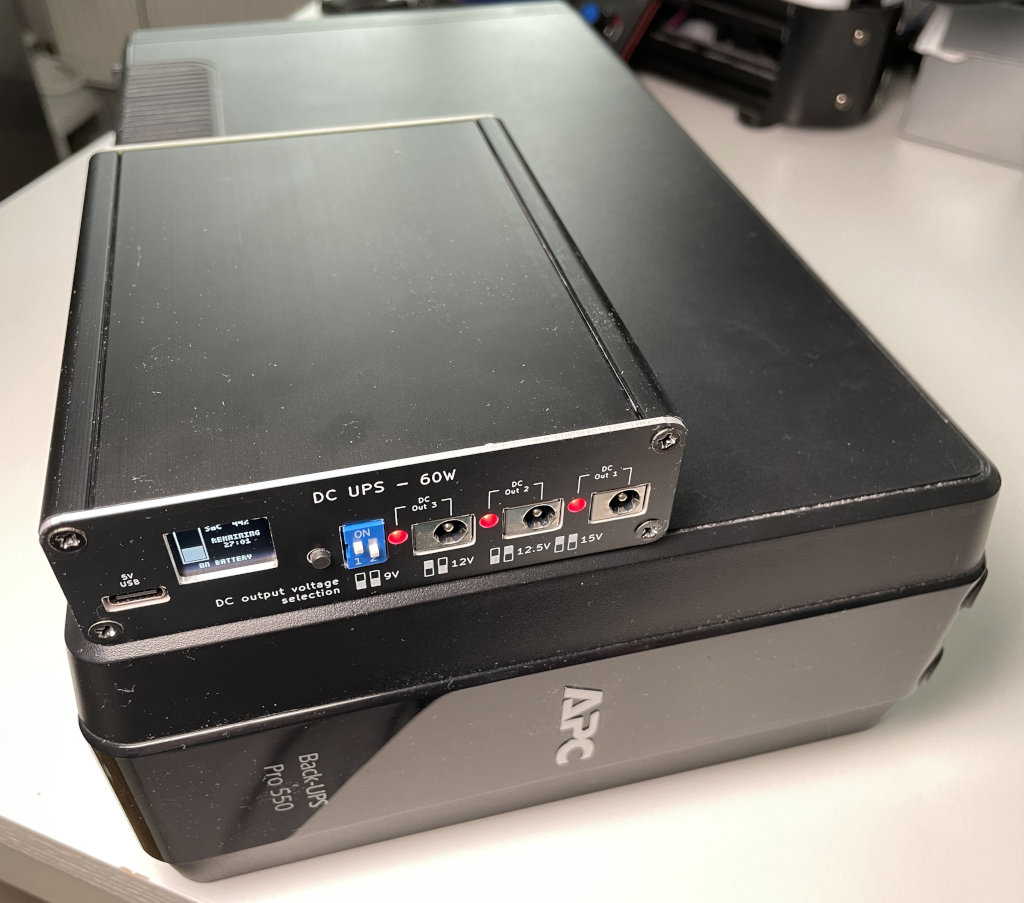
Finally the DC UPS is a lot smaller than available AC UPS options. The
following picture shows a comparison between the AC UPS I have been using
before and the DC UPS:
Rev B is still more of a prototype than I'd like. This is the list of currently know issues:
| Qty | Value | Footprint | References |
|---|---|---|---|
| 33 | 100kR | Resistor_SMD:R_0402_1005Metric | R15, R26, R27, R101, R102, R104, R105, R106, R107, R108, R109, R110, R111, R112, R116, R131 +17 |
| 33 | 100nF | Capacitor_SMD:C_0402_1005Metric | C1, C2, C3, C4, C5, C13, C16, C24, C25, C26, C30, C42, C45, C47, C48, C101 +17 |
| 30 | 10k | Resistor_SMD:R_0402_1005Metric | R14, R20, R51, R53, R103, R113, R114, R115, R118, R119, R121, R126, R127, R128, R129, R132 +14 |
| 15 | 100nF HV | Capacitor_SMD:C_0603_1608Metric | C7, C8, C9, C10, C11, C14, C34, C41, C43, C44, C46, C54, C72, C85, C87 |
| 14 | 22uF | Capacitor_SMD:C_0805_2012Metric | C28, C29, C31, C38, C39, C40, C52, C55, C56, C57, C70, C74, C75, C94 |
| 11 | 1uF | Capacitor_SMD:C_0402_1005Metric | C12, C17, C18, C27, C60, C62, C63, C64, C83, C97, C98 |
| 11 | 2N7002 | Package_TO_SOT_SMD:SOT-23 | Q11, Q13, Q14, Q15, Q16, Q20, Q22, Q26, Q31, Q34, Q37 |
| 10 | 5.1k | Resistor_SMD:R_0402_1005Metric | R8, R9, R12, R18, R22, R97, R98, R120, R124, R125 |
| 8 | 100R | Resistor_SMD:R_0402_1005Metric | R2, R3, R69, R99, R100, R122, R123, R130 |
| 8 | 1R | Resistor_SMD:R_0402_1005Metric | R37, R38, R44, R45, R80, R82, R89, R91 |
| 8 | AO4407A | Package_SO:SOIC-8_3.9x4.9mm_P1.27mm | Q8, Q10, Q19, Q21, Q23, Q32, Q35, Q38 |
| 7 | 10uF | Capacitor_SMD:C_0805_2012Metric | C20, C21, C22, C23, C35, C36, C37 |
| 7 | MMBT3904 | Package_TO_SOT_SMD:SOT-23 | Q12, Q18, Q28, Q29, Q30, Q33, Q36 |
| 6 | 10mR | Resistor_SMD:R_0805_2012Metric | R19, R25, R42, R43, R81, R90 |
| 4 | 220uF | Capacitor_SMD:CP_Elec_6.3x7.7 | C49, C50, C80, C84 |
| 4 | 50R | Resistor_SMD:R_0402_1005Metric | R66, R68, R70, R71 |
| 4 | AON7544 | Package_DFN_FET:DFN-8-FET_3x3mm_P0.65mm | Q1, Q3, Q4, Q5 |
| 4 | INA219AxD | Package_SO:SOIC-8_3.9x4.9mm_P1.27mm | U5, U6, U14, U15 |
| 4 | P6SMB18CA | Diode_SMD:D_SMB | D6, D9, D10, D11 |
| 4 | RED | LED_Indicator:LED_Indicator_RED_MHK1373CRBDT | D8, D12, D13, D14 |
| 3 | 100R 0805 | Resistor_SMD:R_0805_2012Metric | R4, R5, R11 |
| 3 | 100kR | Resistor_SMD:R_1206_3216Metric | R75, R85, R96 |
| 3 | 10MR | Resistor_SMD:R_0402_1005Metric | R6, R10, R13 |
| 3 | 1N4148WS | Diode_SMD:D_SOD-323 | D1, D2, D3 |
| 3 | 1nF 500V | Capacitor_SMD:C_1206_3216Metric | C69, C82, C89 |
| 3 | 2.2uF | Capacitor_SMD:C_0603_1608Metric | C6, C53, C103 |
| 3 | 22nF | Capacitor_SMD:C_0402_1005Metric | C95, C104, C105 |
| 3 | 5A | Fuse:Fuse_1206_3216Metric | F2, F3, F4 |
| 3 | LM75B | Package_SO:MSOP-8_3x3mm_P0.65mm | U2, U7, U13 |
| 3 | Output 2.0mm | Connector_BarrelJack_LCSC:BarrelJack_2.0mm_DC-044B | J1, J2, J3 |
| 2 | 1.5kR | Resistor_SMD:R_0402_1005Metric | R64, R79 |
| 2 | 100pF | Capacitor_SMD:C_0402_1005Metric | C15, C67 |
| 2 | 10R | Resistor_SMD:R_0402_1005Metric | R23, R24 |
| 2 | 12kR | Resistor_SMD:R_0402_1005Metric | R67, R78 |
| 2 | 18kR | Resistor_SMD:R_0402_1005Metric | R17, R21 |
| 2 | 18pF | Capacitor_SMD:C_0402_1005Metric | C58, C76 |
| 2 | 20pF | Capacitor_SMD:C_0402_1005Metric | C90, C91 |
| 2 | 330R | Resistor_SMD:R_0402_1005Metric | R72, R73 |
| 2 | 50R | Resistor_SMD:R_2512_6332Metric | R47, R48 |
| 2 | 56kR | Resistor_SMD:R_0402_1005Metric | R30, R92 |
| 2 | AO3401A | Package_TO_SOT_SMD:SOT-23 | Q2, Q25 |
| 2 | CSD17308Q3 | Package_DFN_FET:DFN-8-FET_3x3mm_P0.65mm | Q6, Q7 |
| 2 | GRN | LED_SMD:LED_0603_1608Metric | D19, D20 |
| 2 | MMBT5401 | Package_TO_SOT_SMD:SOT-23 | Q9, Q24 |
| 2 | MountingHole | ToolingHole:ToolingHole_JLCSMT | H1, H2 |
| 2 | P6SMB6.8CA | Diode_SMD:D_SMB | D7, D16 |
| 2 | RED | LED_SMD:LED_0603_1608Metric | D18, D22 |
| 2 | USB_C_Receptacle_USB2.0 | Connector_USB:USB_C_Receptacle_Palconn_UTC16-G | J6, J9 |
| 2 | YEL | LED_SMD:LED_0603_1608Metric | D17, D21 |
| 1 | 10A | Fuse:Fuse_1206_3216Metric | F1 |
| 1 | 10R | Resistor_SMD:R_1206_3216Metric | R88 |
| 1 | 10uF LV | Capacitor_SMD:C_0402_1005Metric | C100 |
| 1 | 12MHz (DNP) | Crystal:Crystal_SMD_3225-4Pin_3.2x2.5mm | Y1 |
| 1 | 1455L1201BK | Case:1455L1201BK | CASE1 |
| 1 | 150k | Resistor_SMD:R_0402_1005Metric | R28 |
| 1 | 15kR | Resistor_SMD:R_0402_1005Metric | R40 |
| 1 | 180kR | Resistor_SMD:R_0603_1608Metric | R34 |
| 1 | 18650 | battery-holder-keystone:SMD-1048-dual-18650 | B1 |
| 1 | 1mR | Resistor_SMD:R_1206_3216Metric | R1 |
| 1 | 1uH | Inductor_SMD:L_Bourns_SRP7028A_7.3x6.6mm | L2 |
| 1 | 2.2uH | Inductor_SMD:L_Taiyo-Yuden_MD-4040 | L1 |
| 1 | 220kR | Resistor_SMD:R_0402_1005Metric | R36 |
| 1 | 22kR | Resistor_SMD:R_0402_1005Metric | R55 |
| 1 | 300R | Resistor_SMD:R_1206_3216Metric | R7 |
| 1 | 390kR | Resistor_SMD:R_0603_1608Metric | R117 |
| 1 | 39kR | Resistor_SMD:R_0402_1005Metric | R16 |
| 1 | 4.7uF | Capacitor_SMD:C_0402_1005Metric | C32 |
| 1 | 4.7uF HV | Capacitor_SMD:C_0603_1608Metric | C102 |
| 1 | 4.7uH | Inductor_SMD:L_1008_2520Metric | L3 |
| 1 | 4.7uH | Inductor_SMD:L_Bourns_SRP7028A_7.3x6.6mm | L4 |
| 1 | 470pF | Resistor_SMD:R_0402_1005Metric | C61 |
| 1 | 47kR | Resistor_SMD:R_0603_1608Metric | R32 |
| 1 | 47nF HV | Capacitor_SMD:C_0603_1608Metric | C19 |
| 1 | 680pF | Capacitor_SMD:C_0603_1608Metric | C33 |
| 1 | 74HC595 | Package_SO:SOIC-16_3.9x9.9mm_P1.27mm | U11 |
| 1 | 750kR | Resistor_SMD:R_0603_1608Metric | R39 |
| 1 | AO3400A | Package_TO_SOT_SMD:SOT-23 | Q17 |
| 1 | B5819W | Diode_SMD:D_SOD-123 | D15 |
| 1 | BAV70 | Package_TO_SOT_SMD:SOT-23 | D4 |
| 1 | BQ24715 | Package_DFN_QFN:QFN-20-1EP_3.5x3.5mm_P0.5mm_EP2x2mm_ThermalVias | U3 |
The 324 most common of 351 parts.
It measures 140 × 100 mm and has 4 copper layers, 1.66 mm thick.
351 parts, built around the 74HC595, AO4407A, MMBT3904 and AON7544. The full list of its parts is on this page, with links to each part's symbol and footprint where PCBKit's library has them.
From the TobleMiner/DC-UPS repository on GitHub, at the commit this page was made from: the board is dc-usv.kicad_pcb and its schematic backpanel/backpanel.kicad_sch. PCBKit opens the board in the browser, with nothing to install.
Its repository publishes it under the CERN-OHL-P-2.0 licence: you may reuse it on that licence's terms (keep the author's notice, and for a copyleft licence share your changes alike).

cjheath/jlcbasic
JLC Basic parts library for Kicad fetched and converted from EasyEDA


SteveCooling/MidiKeys
Will be a complete board with decoders for multiplexed sampling of analog sources and up to 61-key keybeds


rusefi/hw_microRusEfi
microRusEfi board for rusEfi ECU
