
2 layers47.8 × 64.9 mm
Motor PCB
Loredati-svg/ClockClock24
ClockClock 24 replica: 24 analog clocks showing digital time. ESP32-S3 controllers with VID6606 stepper drivers, auto-addressed I2C bus and VID28-05 dual-shaft motors. KiCad 10.
4 parts

 Loredati-svg/ClockClock24
ClockClock 24 replica: 24 analog clocks showing digital time. ESP32-S3 controllers with VID6606 stepper drivers, auto-addressed I2C bus and VID28-05 dual-shaft motors. KiCad 10.
ClockClock24 is an open-source printed circuit board by Loredati-svg, from the Loredati-svg/ClockClock24 repository on GitHub. It is a 4-layer board of 78.9 × 51 mm with 46 parts on 82 nets, routed with 554 tracks and 127 vias.
It is built around the ESP32-S3-WROOM-1-N8, AP7361C-33E and USBLC6-2SC6, with the SMAJ5.0A and SS54 among its other parts. Its parts include 12 capacitors, 11 resistors, 7 connectors, 5 ICs and 3 diodes. It belongs with the robots and motor control and lEDs and displays boards and the ESP32 boards of this library.






A personal re-implementation of the ClockClock 24 kinetic sculpture by Humans Since 1982: 24 analog clocks in a 3 × 8 grid whose hands move together to show the time in digital form.
Inspired by Vallasc/clockclock24-replica, with a redesigned architecture: ESP32-S3 controllers, USB-C on every board, an auto-addressed I2C bus and separate motor boards.
For personal, non-commercial use only. All design rights belong to Humans Since 1982.
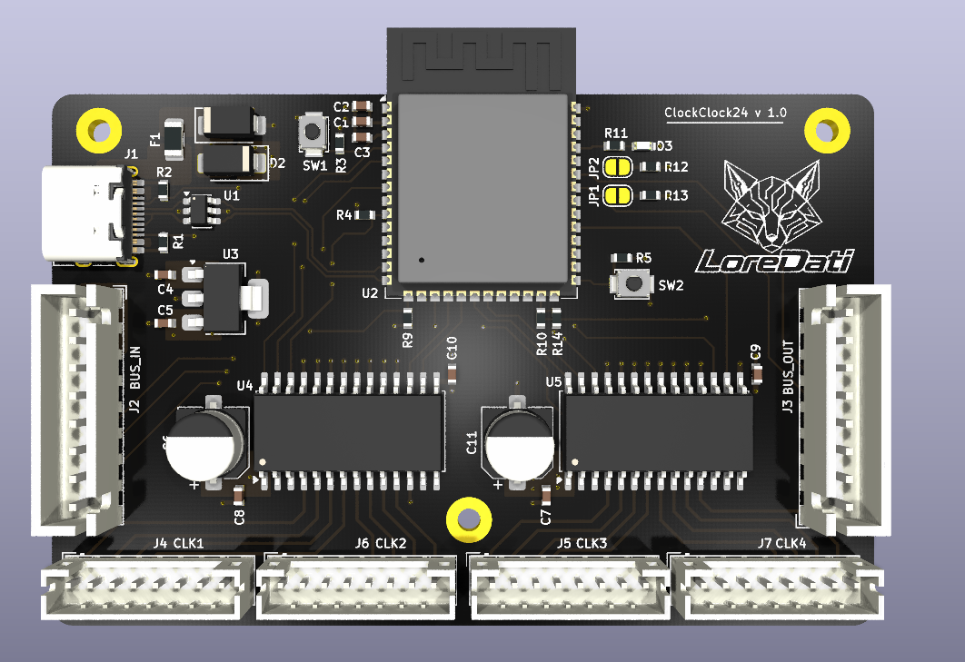
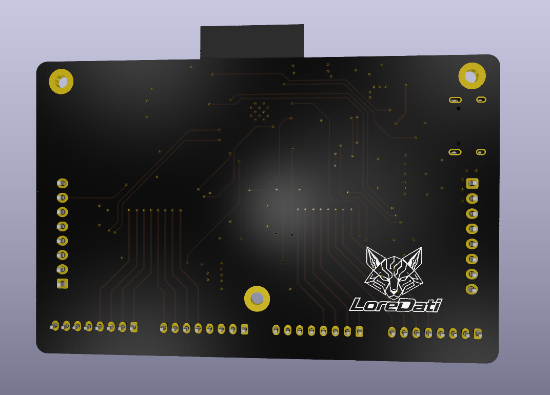
Controller board, rev A (3D render, top and bottom)
6 identical controller boards (2 per row), each driving 4 clocks (8 motors) via cables to 24 passive motor boards, one behind each clock.
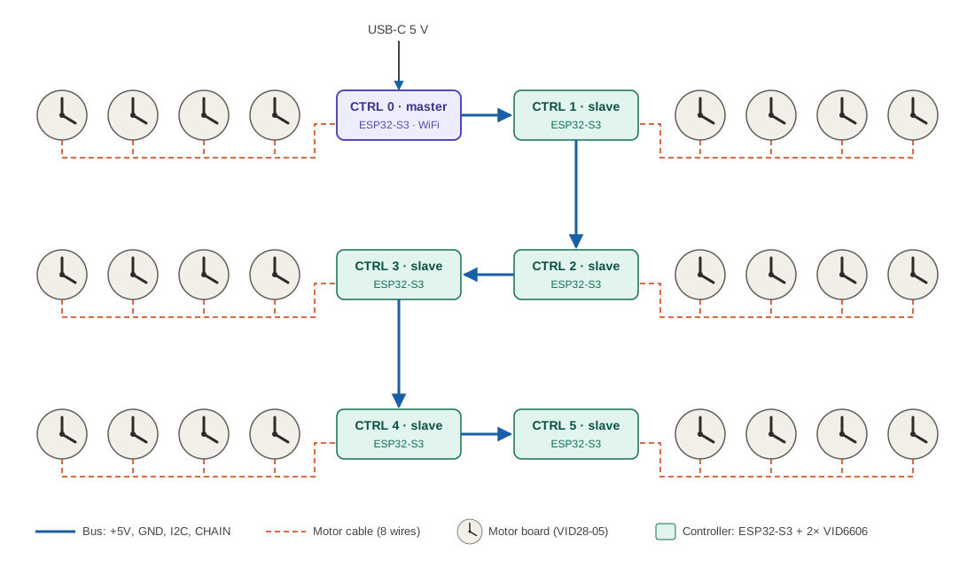
USB-C (5 V, programming + debug via native USB) → protection → +5 V rail → 2× VID6606 drivers and the bus; AP7361C LDO → 3.3 V for the ESP32-S3-WROOM-1-N8.
A minimal board with only the motor and its connector: one VID28-05 / BKA30D-R5 dual-shaft stepper (two motors, coaxial shafts, one hand each) and one 8-pin connector. No active parts.
Public documentation on this motor is scarce (mechanical drawings, pin numbering and the 360° no-stop variant all differ between sellers), so the footprint and pinout are being validated on real samples before the board is finalized.
The bus connectors carry +5V, GND, I2C_SDA (IO41), I2C_SCL (IO42) and a CHAIN line.
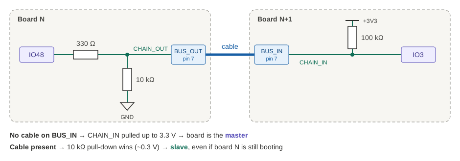
BUS_IN → CHAIN_IN high → master. Cable present → low → slave, even if the upstream board is still booting.CHAIN_OUT. Each board answers on a temporary I2C address and receives its permanent one, so addresses match the physical order automatically.Bus – BUS_IN / BUS_OUT (JST-XH 8 pin, straight cables)
| 1 | 2 | 3 | 4 | 5 | 6 | 7 | 8 |
|---|---|---|---|---|---|---|---|
| +5V | +5V | GND | GND | SDA | SCL | CHAIN_IN / OUT | GND |
Motors – CLK1…CLK4 (JST-PH 8 pin): pins 1–4 = first motor (OUT1–4), pins 5–8 = second motor. Same pinout on every connector and motor board, so all cables and motor boards are interchangeable. Using different connector families for bus and motors makes it impossible to plug a bus cable into a motor output.
VID_RST is pulled low after each move. The 180:1 gearbox holds the hands, which saves power and heat.-DARDUINO_USB_CDC_ON_BOOT=1 (TXD0 is used for the status LED).| Qty | Value | Footprint | References |
|---|---|---|---|
| 5 | 100n | eCapacitor:0603 | C2, C7, C8, C9, C10 |
| 4 | 10k | eResistor:0603 | R3, R4, R5, R14 |
| 3 | MountingHole | MountingHole:MountingHole_2.2mm_M2_Pad | H1, H3, H4 |
| 2 | 100u | Capacitor_SMD:CP_Elec_6.3x5.4 | C6, C11 |
| 2 | 1u | eCapacitor:0603 | C3, C12 |
| 2 | 4k7 | eResistor:0603 | R12, R13 |
| 2 | 4u7 | eCapacitor:0603 | C4, C5 |
| 2 | 5k1 | eResistor:0603 | R1, R2 |
| 2 | SW_Push | Button_Switch_SMD:SW_SPST_B3U-1000P | SW1, SW2 |
| 2 | VID6606 | eInterface:SOIC-28W_7.5x17.9mm_P1.27mm | U4, U5 |
| 1 | 100k | eResistor:0603 | R9 |
| 1 | 10u | eCapacitor:0603 | C1 |
| 1 | 1k | eResistor:0603 | R11 |
| 1 | 330 | eResistor:0603 | R10 |
| 1 | AP7361C-33E | Package_TO_SOT_SMD:SOT-223-3_TabPin2 | U3 |
| 1 | BUS_IN | Connector_JST:JST_XH_B8B-XH-A_1x08_P2.50mm_Vertical | J2 |
| 1 | BUS_OUT | Connector_JST:JST_XH_B8B-XH-A_1x08_P2.50mm_Vertical | J3 |
| 1 | CLK1 | Connector_JST:JST_PH_B8B-PH-K_1x08_P2.00mm_Vertical | J4 |
| 1 | CLK2 | Connector_JST:JST_PH_B8B-PH-K_1x08_P2.00mm_Vertical | J6 |
| 1 | CLK3 | Connector_JST:JST_PH_B8B-PH-K_1x08_P2.00mm_Vertical | J5 |
| 1 | CLK4 | Connector_JST:JST_PH_B8B-PH-K_1x08_P2.00mm_Vertical | J7 |
| 1 | ESP32-S3-WROOM-1 | RF_Module:ESP32-S3-WROOM-1 | U2 |
| 1 | LED | eLED:0603_pol | D3 |
| 1 | PU_SCL | Jumper:SolderJumper-2_P1.3mm_Open_RoundedPad1.0x1.5mm | JP2 |
| 1 | PU_SDA | Jumper:SolderJumper-2_P1.3mm_Open_RoundedPad1.0x1.5mm | JP1 |
| 1 | Polyfuse | Fuse:Fuse_1206_3216Metric | F1 |
| 1 | SMAJ5.0A | Diode_SMD:D_SMA | D2 |
| 1 | SS54 | PCM_JLCPCB:D_SMA | D1 |
| 1 | USBLC6-2SC6 | Package_TO_SOT_SMD:SOT-23-6 | U1 |
| 1 | USB_C_Receptacle_USB2.0_16P | Connector_USB:USB_C_Receptacle_HRO_TYPE-C-31-M-12 | J1 |
It measures 78.9 × 51 mm and has 4 copper layers, 1.6 mm thick.
46 parts, built around the ESP32-S3-WROOM-1-N8, AP7361C-33E, USBLC6-2SC6 and SMAJ5.0A. The full list of its parts is on this page, with links to each part's symbol and footprint where PCBKit's library has them.
From the Loredati-svg/ClockClock24 repository on GitHub, at the commit this page was made from: the board is Hardware/Controller/ClockClock24.kicad_pcb and its schematic Hardware/Controller/ClockClock24.kicad_sch. PCBKit opens the board in the browser, with nothing to install.
Its repository states no licence, so its author keeps all rights: ask Loredati-svg before reusing the design.
Loredati-svg/ClockClock24
ClockClock 24 replica: 24 analog clocks showing digital time. ESP32-S3 controllers with VID6606 stepper drivers, auto-addressed I2C bus and VID28-05 dual-shaft motors. KiCad 10.

tombueng/hilprobe
HILprobe: multi-function UUT probe for hardware-in-the-loop testing - RS-485, CAN FD, logic analyzer, 4-ch scope, two programmable UUT supplies. KiCad 10, 6 layers, RP2350B + ESP32-S3.

Majorwhiskey/gps-lora
Theoros is a USB-C GPS logger and LoRa tracker built on the ESP32-S3. It logs 1 Hz u-blox M10 fixes to microSD, shows status on an OLED and sends AES-128-CCM encrypted position over 868 MHz LoRa.

Gordon-coder/Robotic-Arm-Fallen-2026
Robotic Arm project for Hack Club's Fallen Event 2026

hoeken/frothfet
Yarrboard load controller board with current sense, volt sense, fuses, and sender support.


sat-wik/HardFuzz
Runs on a Digilent Cmod A7 (Xilinx Artix-7) wired inline with a NUCLEO-F446RE as the device under test. Injector BOM ≈ $40.

nathanfraske/CEC-Platform
ONE board file, kept current by the wave (owner directive 2026-07-25: "the current best should be placed into a candidate folder per board and kept current with only one board ideally so we have a reference").

yedidiaSch/FalconDrone
[IN PROGRESS] High-performance flight controller for quadcopters, providing real-time stabilization and attitude control using FreeRTOS and C++ on STM32