
2 layers119 × 47.5 mm
 sat-wik/HardFuzz
Runs on a Digilent Cmod A7 (Xilinx Artix-7) wired inline with a NUCLEO-F446RE as the device under test. Injector BOM ≈ $40.
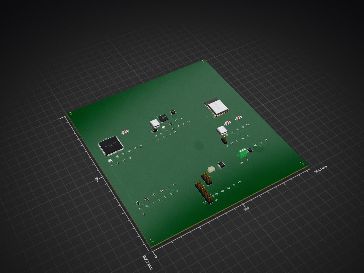
Hardfuzz v1 original is an open-source printed circuit board by sat-wik, from the sat-wik/HardFuzz repository on GitHub, published under the MIT licence. It is a 4-layer board of 184.1 × 197.7 mm with 84 parts on 228 nets, routed with 930 tracks and 195 vias.
It is built around the ICE40HX4K-TQ144, ESP32-S3-WROOM-1-N8 and SN65HVD230D, with the TLV62566DBV, FT2232HQ and TXS0108EPW among its other parts. Its parts include 29 capacitors, 24 resistors, 8 ICs, 7 connectors and 5 diodes. It belongs with the ESP32 and FPGA and CPLD boards of this library.


A ~$40 FPGA fault-injection module for safety-critical embedded testing. Inject precisely-targeted hardware faults — SPI bit-flips, I2C clock stretching, CAN frame corruption — into a live bus under host control, run scriptable coverage-guided campaigns, and get a pass/fail evidence report. An open, low-cost alternative to the $30K–$80K bench tools (Lauterbach, Kraken, XCITE) that ISO 26262 / IEC 61508 fault- injection evidence usually demands.
Runs on a Digilent Cmod A7 (Xilinx Artix-7) wired inline with a NUCLEO-F446RE as the device under test. Injector BOM ≈ $40.
| Capability | Status |
|---|---|
| SPI bit-flip injection (target frame + bit) | ✅ on hardware |
| I2C clock-stretch injection (target byte + duration) | ✅ on hardware — 36-scenario sweep passes |
| CAN frame corruption (bad CRC / stuff / form error) | ✅ in simulation — needs a transceiver on hardware |
hardfuzz campaign engine — JSON campaigns, coverage-guided scheduling, live serial execution, JSON/CSV/HTML reports with IEC 61508 traceability | ✅ built + tested |
Every RTL core self-checks in simulation (make sim); the C++ host layer has its own
test suite (make -C host). See HardFuzz_Refined_Plan.md
for the design and month-by-month build log,
docs/HardFuzz_v1_Spec.md for where it's headed as a
product (board I/O, attach modes, out-of-box experience), and
docs/HardFuzz_v2_Standalone.md for the computer-free
v2 — an on-board ESP32 runs the campaign engine and streams results to a phone app over BLE.
rtl/            Verilog sources
  uart/         UART RX/TX (the host link over the Cmod's FT2232 bridge)
  ctrl/         ctrl_regs.v — UART->register-file command FSM (host control)
  spi/          spi_slave.v — mode-0 SPI slave, the DUT-facing bus (echo response)
  i2c/          i2c_slave.v — I2C slave (write xactions) with clock-stretch hook
  can/          frame_corrupt.v — CAN bus monitor + force-dominant injector
  inject/       bitflip_inj.v (SPI bit flip), timing_distort.v (I2C clock stretch)
  timing/       pulse_meter.v — scope-free timing measurement
  hardfuzz_top.v    bring-up top: LED heartbeat + UART echo
  spi_inject_top.v  Month 1 integration: host-armed SPI bit-flip injection
  i2c_inject_top.v  Month 2 integration: host-armed I2C clock-stretch injection
  can_inject_top.v  Month 2 integration: host-armed CAN frame corruption (sim-only)
  multi_inject_top.v Month 4: combined SPI+I2C in one bitstream (reg4 selects protocol)
sim/            testbenches + Icarus runner (primary verifier for now)
constraints/    cmod_a7.xdc  (pinout; SPI on Pmod JA)
scripts/        Vivado batch build / program TCL
firmware/       STM32 C — SPI master (main.c) + I2C master (main_i2c.c)
host/           arm.py + Month 3 C++ campaign library (include/hardfuzz/) & `hardfuzz` CLI
hardware/       HardFuzz v1 custom-PCB design — schematic spec + BOM (KiCad capture next)
docs/ timing-verification.md and design notesbrew install icarus-verilog surfer.
(Surfer is the maintained, native-arm64 waveform viewer; the old gtkwave cask is
discontinued and x86-only.).bit back. See docs/vivado-cloud.md.brew install openfpgaloader) to program the Cmod A7 from
macOS natively — make prog. Board string: cmoda7_35t (or cmoda7_15t).Simulate first — no board required:
make sim         # UART echo self-check   -> "ALL TESTS PASSED"
make sim-pulse   # timing meter self-check
make wave        # run a sim and open the waveform in Surfer
                 #   (pick another: make wave WAVE=tb_pulse_meter)
                 #   how to read it: docs/waveforms.md
Then, to get onto hardware (Vivado on Linux/cloud, program from the Mac):
make bit         # ON A LINUX/CLOUD BOX: synth + P&R + bitstream (docs/vivado-cloud.md)
                 #   copy build/vivado/spi_inject_top.bit back to the Mac
make prog        # ON THE MAC: openFPGALoader loads the .bit to the Cmod A7
On the board, led[0] blinks at ~1 Hz (clock/toolchain alive). Open the Cmod's USB
serial port at 115200 8N1 and type — every character echoes back and led[1]
toggles (host link alive).
You'll add a logic analyzer and oscilloscope later. Until then,
docs/timing-verification.md covers how to measure
digital fault timing on-chip (cycle counting, loopback calibration, the ILA, and a
reserved trig_out pin) and — importantly — what stays invisible until the
instruments arrive.
spi_inject_top is the FPGA-as-SPI-slave design from the refined plan. The host arms
a target over UART; the STM32 (SPI master) clocks frames; the injector flips the
chosen bit of the MISO echo; the STM32 reads back the corrupted byte. Register map:
| Access | Addr | Meaning |
|---|---|---|
| W/R | reg0 | control: bit0 inj_enable, bit1 clr_frame (pulse), bit2 line_sel (rsvd) |
| W/R | reg1 | target_frame[7:0] |
| W/R | reg2 | target_frame[15:8] |
| W/R | reg3 | target_bit (0=LSB .. 7=MSB) |
| R | 0x80 | frame_idx[7:0] (bytes seen since reset/clr) |
| R | 0x81 | frame_idx[15:8] |
| R | 0x82 | flip_count |
UART wire protocol: W(0x57) addr data to write; R(0x52) addr to read one byte.
E.g. to flip frame 5, bit 3: W 01 05, W 02 00, W 03 03, W 00 01.
tb_spi_inject proves this end-to-end in simulation (arm over UART → clock 8 frames →
only frame 5 / bit 3 flips, flip_count == 1). All four testbenches pass under Icarus:
make sim.
i2c_inject_top is the FPGA-as-I2C-slave counterpart to the SPI design. The host arms
a target byte + stretch length over UART; the STM32 (I2C master) writes a transaction;
on the target byte the slave holds SCL low for the programmed time — an abnormal clock
stretch that stalls the master and trips its timeout. Register map:
| Access | Addr | Meaning |
|---|---|---|
| W/R | reg0 | control: bit0 distort_enable, bit1 clr (reset stretch counter) |
| W/R | reg1 | target_byte (0=address, 1=first data byte, 2=second, ...) |
| W/R | reg2 | stretch_len[7:0] |
| W/R | reg3 | stretch_len[15:8] (SCL-low hold in 12 MHz cycles; 1200 ≈ 100 µs) |
| R | 0x80 | byte_index |
| R | 0x81/0x82 | stretch_count low/high |
I2C is open-drain on Pmod JA7 (SCL) / JA8 (SDA); slave address 0x42. tb_i2c_inject
proves it end-to-end in sim (arm over UART → I2C write → SCL stretched only on the
target byte, ~20 µs, stretch_count == 1). RTL is sim-verified; not yet run on
hardware — needs STM32 I2C-master firmware (the current firmware is SPI-only) and a
separate bitstream (make bit TOP=i2c_inject_top).
can_inject_top corrupts CAN frames without being the transmitter, exploiting the
bus's wired-AND rule: a dominant bit always wins. frame_corrupt watches the bus
(RXD from a transceiver), tracks the bit index from Start-Of-Frame, and on a host-armed
bit forces the bus dominant for width bits. Aim decides the fault: a data/CRC bit →
bad CRC; ≥6 forced bits → bit-stuffing violation; a bit in the EOF → form error.
| Access | Addr | Meaning |
|---|---|---|
| W/R | reg0 | control: bit0 enable, bit1 clr |
| W/R | reg1 | target_bit[7:0] (index from SOF; SOF = bit 0) |
| W/R | reg2 | target_bit[15:8] |
| W/R | reg3 | width (consecutive bits to force dominant; ≥6 = stuff error) |
| R | 0x80/0x81 | corrupt_count lo/hi |
| R | 0x82/0x83 | frame_count lo/hi |
Arm with arm.py … can --bit 20 --width 1. tb_can_inject proves it in sim (targeted
bits forced dominant, untargeted bits untouched, corrupt_count correct).
SIM-ONLY — hardware needs an SN65HVD230 transceiver on can_txd/can_rxd (shares
Pmod JA7/JA8) plus STM32 bxCAN firmware; neither exists yet.
Working on hardware ✅ — the Month 1 MVP runs end to end on a Cmod A7 + NUCLEO-F446RE.
Host arms a target over UART (arm.py), the STM32 clocks SPI frames, the FPGA injects
exactly one bit on the chosen frame, and the STM32 reads back and reports the fault
(e.g. frame 5 bit 3: 0xA4 → 0xAC, all other frames clean). Design is in the Cmod's
flash (make prog-flash), so it survives power cycles.
Bring-up gotchas (both fixed): make prog loads to volatile SRAM — use
prog-flash to persist; and the Cmod UART pins are uart_rxd_out=J18,
uart_txd_in=J17 (do not swap — it silently kills the register interface while SPI
still works).
Both the SPI bit-flip (Month 1) and I2C clock-stretch (Month 2) cores now run
end to end on hardware — host arms over UART, the STM32 master runs a transaction, the
FPGA injects, and the master catches the fault (SPI: 0xA4→0xAC; I2C: byte hits the
master's timeout at 2 ms while the slave holds SCL low).
Verified in sim + hardware: spi_slave, bitflip_inj, spi_inject_top + SPI
firmware; i2c_slave, timing_distort, i2c_inject_top + I2C firmware; ctrl_regs,
arm.py.
Combined SPI+I2C — validated on hardware: multi_inject_top (one bitstream, reg4
selects protocol) + main_multi.c (one firmware, S/I/R commands) let a single
mixed SPI+I2C campaign run live with zero reflashing — wire both buses once, and
each fault swaps the active protocol on both sides. Proven end to end with
host/campaigns/multi.json (7/7 pass).
Verified in sim (not yet on hardware): frame_corrupt, can_inject_top — needs an
SN65HVD230 transceiver to run on hardware.
Month 3 C++ campaign layer (host/) — built + self-tested: header-only C++17
(FaultCampaign, CoverageTracker, coverage-guided Scheduler, RegClient,
JSON/CSV reports with IEC 61508 traceability) + the hardfuzz CLI, with live mode:
it arms the FPGA over the Cmod UART and drives the STM32 run-command firmware (send
'R' → RESULT line) for real pass/fail verdicts. Verified against a mock transport
(make -C host, 18 checks); the run-command firmware is in main.c/main_i2c.c.
Next: validate live hardfuzz run on the boards (dry run + serial parsing are
tested; the end-to-end serial path needs a hardware pass); CAN hardware bring-up when
the SN65HVD230s arrive; HTML report + coverage heatmap. trig_out is ready for a scope.
| Qty | Value | Footprint | References |
|---|---|---|---|
| 13 | 100nF | Capacitor_SMD:C_0402_1005Metric | C20, C30, C31, C41, C43, C44, C48, C50, C51, C52, C53, C54, C61 |
| 7 | 10k | Resistor_SMD:R_0402_1005Metric | R20, R40, R43, R50, R52, R60, R61 |
| 6 | 10uF | Capacitor_SMD:C_0402_1005Metric | C1, C2, C40, C47, C60, C63 |
| 4 | 22uF | Capacitor_SMD:C_0402_1005Metric | C3, C4, C5, C6 |
| 4 | 5.1k | Resistor_SMD:R_0402_1005Metric | R41, R42, R63, R64 |
| 4 | MountingHole_2.2mm_M2 | MountingHole_2.2mm_M2 | H1, H2, H3, H4 |
| 3 | 100k | Resistor_SMD:R_0402_1005Metric | R30, R33, R34 |
| 2 | 18pF | Capacitor_SMD:C_0402_1005Metric | C45, C46 |
| 2 | 1uF | Capacitor_SMD:C_0402_1005Metric | C32, C62 |
| 2 | 200k | Resistor_SMD:R_0402_1005Metric | R3, R4 |
| 2 | 330 | Resistor_SMD:R_0402_1005Metric | R53, R62 |
| 2 | 4.7k | Resistor_SMD:R_0402_1005Metric | R31, R32 |
| 2 | 60R | Resistor_SMD:R_0402_1005Metric | R21, R22 |
| 2 | TLV62566 | Package_TO_SOT_SMD:SOT-23-5 | U6, U7 |
| 2 | USB-C | Connector_USB:USB_C_Receptacle_GCT_USB4085 | J1, J6 |
| 1 | 1.5uH | Inductor_SMD:L_0805_2012Metric | L2 |
| 1 | 12MHz | Crystal:Crystal_SMD_3225-4Pin_3.2x2.5mm | Y2 |
| 1 | 12MHz | Oscillator:Oscillator_SMD_Abracon_ASE-4Pin_3.2x2.5mm | Y1 |
| 1 | 2.2uH | Inductor_SMD:L_0805_2012Metric | L1 |
| 1 | 4.7nF | Capacitor_SMD:C_0402_1005Metric | C21 |
| 1 | 4.7uF | Capacitor_SMD:C_0402_1005Metric | C42 |
| 1 | 412k | Resistor_SMD:R_0402_1005Metric | R1 |
| 1 | 91k | Resistor_SMD:R_0402_1005Metric | R2 |
| 1 | BLE | LED_SMD:LED_0603_1608Metric | D50 |
| 1 | BOOT | Button_Switch_SMD:SW_SPST_CK_RS282G05A3 | SW3 |
| 1 | BUS | Connector_PinHeader_2.54mm:PinHeader_2x10_P2.54mm_Vertical | J3 |
| 1 | CAN | TerminalBlock_Phoenix:TerminalBlock_Phoenix_MPT-0,5-3-2.54_1x03_P2.54mm_Horizontal | J5 |
| 1 | DONE | LED_SMD:LED_0603_1608Metric | D40 |
| 1 | DUT | Connector_PinHeader_2.54mm:PinHeader_1x03_P2.54mm_Vertical | J7 |
| 1 | ESP32-S3-WROOM-1 | RF_Module:ESP32-S3-WROOM-1 | U12 |
| 1 | FT2232HQ | Package_DFN_QFN:QFN-64-1EP_9x9mm_P0.5mm_EP4.35x4.35mm | U2 |
| 1 | ICE40HX4K-TQ144 | Package_QFP:TQFP-144_20x20mm_P0.5mm | U1 |
| 1 | MX25L3233F | Package_SO:SOIC-8_3.9x4.9mm_P1.27mm | U3 |
| 1 | Qwiic | Connector_JST:JST_SH_SM04B-SRSS-TB_1x04-1MP_P1.00mm_Horizontal | J2 |
| 1 | RESET | Button_Switch_SMD:SW_SPST_CK_RS282G05A3 | SW1 |
| 1 | RST | Button_Switch_SMD:SW_SPST_CK_RS282G05A3 | SW2 |
| 1 | SMAJ5.0A | Diode_SMD:D_SOD-923 | D20 |
| 1 | SMAJ5.0A | Diode_SMD:D_SMA | D31 |
| 1 | SN65HVD230 | Package_SO:SOIC-8_3.9x4.9mm_P1.27mm | U9 |
| 1 | SPI/UART | Connector_PinHeader_2.54mm:PinHeader_2x05_P2.54mm_Vertical | J4 |
| 1 | TXS0108EPW | Package_SO:TSSOP-20_4.4x6.5mm_P0.65mm | U10 |
| 1 | USBLC6-2SC6 | Package_TO_SOT_SMD:SOT-23-6 | D30 |
It measures 184.1 × 197.7 mm and has 4 copper layers, 1.6 mm thick.
84 parts, built around the ICE40HX4K-TQ144, ESP32-S3-WROOM-1-N8, SN65HVD230D and TLV62566DBV. The full list of its parts is on this page, with links to each part's symbol and footprint where PCBKit's library has them.
From the sat-wik/HardFuzz repository on GitHub, at the commit this page was made from: the board is hardware/hardfuzz_v1/hardfuzz_v1_original.kicad_pcb and its schematic hardware/hardfuzz_v1/can.kicad_sch. PCBKit opens the board in the browser, with nothing to install.
Its repository publishes it under the MIT licence: you may reuse it on that licence's terms (keep the author's notice, and for a copyleft licence share your changes alike).

Pepa1ZdepaDotC/FPGA-devboard-LATTICE-ICE45HX
Schematic --- ## FPGA - HX for higher performance while maintaining low power consumption - SPI communication between FPGA - MCU - ADC - DAC - One SPI CS broken out - TQ144 for easy soldering

blazer82/gb.fpga
FPGA-based handheld console that plays games from Gameboy cartridges


RubenVoell/iceduino
The basic idea behind this project is to create a simple breakout of an ICE40 FPGA with some LEDs and Buttons to interact with the FPGA and enough resources to run a simple softcore, like a small RISC-V core.

Loredati-svg/ClockClock24
ClockClock 24 replica: 24 analog clocks showing digital time. ESP32-S3 controllers with VID6606 stepper drivers, auto-addressed I2C bus and VID28-05 dual-shaft motors. KiCad 10.

nathanfraske/CEC-Platform
ONE board file, kept current by the wave (owner directive 2026-07-25: "the current best should be placed into a candidate folder per board and kept current with only one board ideally so we have a reference").
