2 layers15.6 × 14.7 mm
 logical/telepathy10
Telepathy is a wireless eeg device.
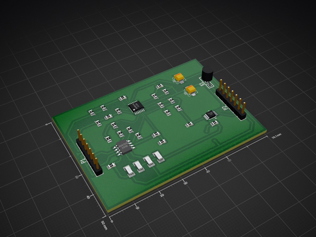
Amp board is an open-source printed circuit board by logical, from the logical/telepathy repository on GitHub. It is a 2-layer board of 70.1 × 50 mm with 35 parts on 24 nets, routed with 237 tracks and 16 vias.
It is built around the AD8618AR, INA128U and AD7694ARM. Its parts include 13 resistors, 12 capacitors, 4 diodes, 3 ICs and 2 connectors. It belongs with the audio and music boards of this library.


THIS PROJECT IS DISCONTINUED FOR NOW.
The research is proving more difficult than I have hoped and there are alternatives available.
This is telepathy the mostly HARDWARE project not telepathy the software project Sorry for my lack of creativity in choosing a name.
This poject contains an EXPERIMENTAL wireless eeg circuit.
This project is under development so it is not working. I welcome suggestions.
The goal is to do brain computer interface experments.I want to make a wireless headband that runs on a battery.
It contains.
I made one pcb but it didn't work. I'm still interested in the project so I am currently doing a complete redesign of the hardware. I will be etching the boards myself they will be single sided SMT and divided in sections.Here are some of the changes I'm planning.
ELECTRODES:
I have 2 designs for active electrodes. Active dry electrodes and active noncontact electrodes. The dry electrodes are based on the openeeg design. The noncontact electrodes are based on a design I found here:
http://www.isn.ucsd.edu/pubs/bsn10.pdf
I'm assuming it is creative commons.
AMPLIFIER BOARD:
The amplifier board is under testing I plan to use one filter for aliasing and filter the rest in software. None
of the resistor and capacitor values are decided yet.
I have the source voltage at 3.3v from a cell phone battery. So far I can pick up a heartbeat .
EEGDATA:
A GUI software program for linux that retreives the data from the /dev/rfcomm0 bluetooth serial terminal and analyzes and displays the data. I started the project in C but it was more convenient to write the data analysis portion in C++.
On my system I use these commands to setup the bluetooth serial port.
#find the address
$hcitool scan
#bind the address
$sudo rfcomm bind rfcomm0 device_address
For BLE
#find the adapter address
$hcitool dev
#find the device address
$sudo hcitool -i hci0 lescan
Then you need to run any programs that access serial terminal as root unless you have sufficient permission.
FIRMWARE:
The firmware is for a PIC microcontroller 16f1788 and a bluetooth serial module hc-05.
I have wrote a bootloader so I can more easily install firmware.The bootloader sets the hc-05 up at 38400 and waits for a program. When the program successfully loads it sets a byte in ee memory.when the FLASH command is sent to the program it erases the byte so the bootloader will again wait for a progam. You can use a standard serial terminal to send the program but you have to set a long delay (~30ms) between characters so the program has time to write. Custom coding the serial interface for the bootloader would be faster but this works for now.
Hopefully I have no glitches in the bootloader or a firmware update could brick the device! If so the glitch would have to be fixed and the bootloader reprogrammed.
The microcontroller first sets up the hc-05 at 230400, then wait for a request.When it receives a request it begins sampling the analog to digital converter and sending the samples to the hc-05.
I have included the makefiles so they should build with the make command but they may require modification . MPLABX should be able to load them as a makefile project but I have not tried.
SCHEMATIC:
I'm developing the amplifier board first. amplifier-board.png is the current design.
DISCLAIMER:
This project is an EXPERIMENT. I make no claims that it actually does anything.It may be harmful to individuals or property. THIS DEVICE AND SOFTWARE MAY BE DANGEROUS. DO NOT BUILD IT.
| Qty | Value | Footprint | References |
|---|---|---|---|
| 5 | 10k | SM0805 | R1, R2, R7, R9, R12 |
| 4 | 100n | SM0805 | C6, C7, C8, C9 |
| 4 | DIODE | SM1206 | D1, D2, D3, D4 |
| 3 | 1M | SM0805 | R5, R6, R10 |
| 2 | 10u | SM0805 | C2, C3 |
| 2 | 1n | SM0805 | C4, C5 |
| 2 | 2.2k | SM0805 | R3, R4 |
| 2 | CAPAPOL | c_elec_4x4.5 | C10, C11 |
| 2 | CONN_7 | SIL-7 | P1, P2 |
| 1 | 100 | SM0805 | R13 |
| 1 | 100k | SM0805 | R8 |
| 1 | 1u | SM0805 | C1 |
| 1 | 200k | SM0805 | R11 |
| 1 | AD8618 | TSSOP14 | U1 |
| 1 | C | SM0805 | C12 |
| 1 | CONN_3 | SIL-3 | K1 |
| 1 | INA128 | SO8N | U3 |
| 1 | ad7694 | MSOP_8 | U4 |


alberto-battistel/Teensy-EIS
Transform your teensy 3.6 (pjrc.com) into an instrument for electrochemical impedance spectroscopy.


shreenandansonu/Electronic-Stethescope
EKOBIT is an electronics stethoscope, a AFE signal board for a digital stethoscope.

TZeng0698/Portable-EEG-with-Modular-Pre-Filtering-for-BCI-Applications
A Low-cost EEG BCI implementation with modular filtering card and ADS1298. The repo contains the PCB files and a guide to design your own(in progress).

Neurotechnology-Exploration-Team/Psylink-NXT
This is intended as a human input device (like a keyboard) that predicts your intention from muscle signals. Using a neural network, trained through a process where you press keys at the exact same time that you make…

Pinheirogustavo/PCB_projects
O gerador de sinais é baseado no AD9850. São gerados dois sinais senoidais e dois sinais quadrados, com banda de frequência entre 1 Hz e 40 MHz.

GiulianoAgostini04/FRED-Project
Real-time concentration monitoring system based on frontal-lobe EEG signals. Features a custom PCB designed with TinkerCAD and KiCad, OpenBCI Ganglion and Arduino UNO for signal acquisition, display, and frequency-band…

It measures 70.1 × 50 mm and has 2 copper layers, 1.6 mm thick.
35 parts, built around the AD8618AR, INA128U and AD7694ARM. The full list of its parts is on this page, with links to each part's symbol and footprint where PCBKit's library has them.
From the logical/telepathy repository on GitHub, at the commit this page was made from: the board is amplifier-board/amp-board.kicad_pcb. PCBKit opens the board in the browser, with nothing to install.
Its repository states no licence, so its author keeps all rights: ask logical before reusing the design.