2 layers69.9 × 33 mm
Lpf ak4497 dual mono
ljufa/rsplayer_hardware
kicad files for rsplayer music player hardware
37 parts2MIT

 ljufa/rsplayer_hardware2
kicad files for rsplayer music player hardware
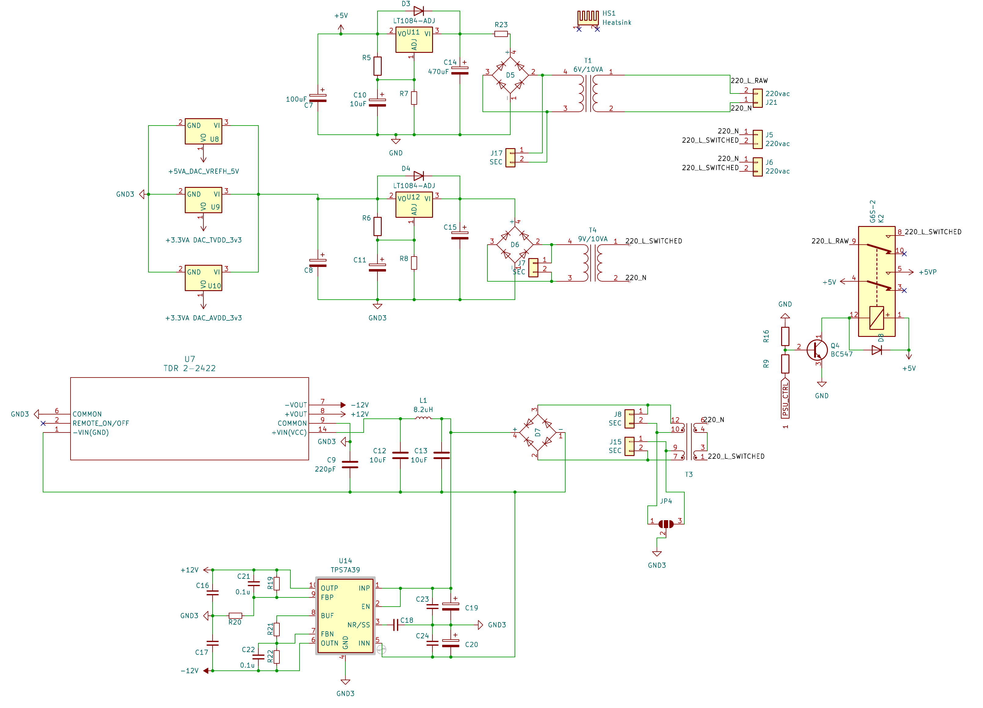
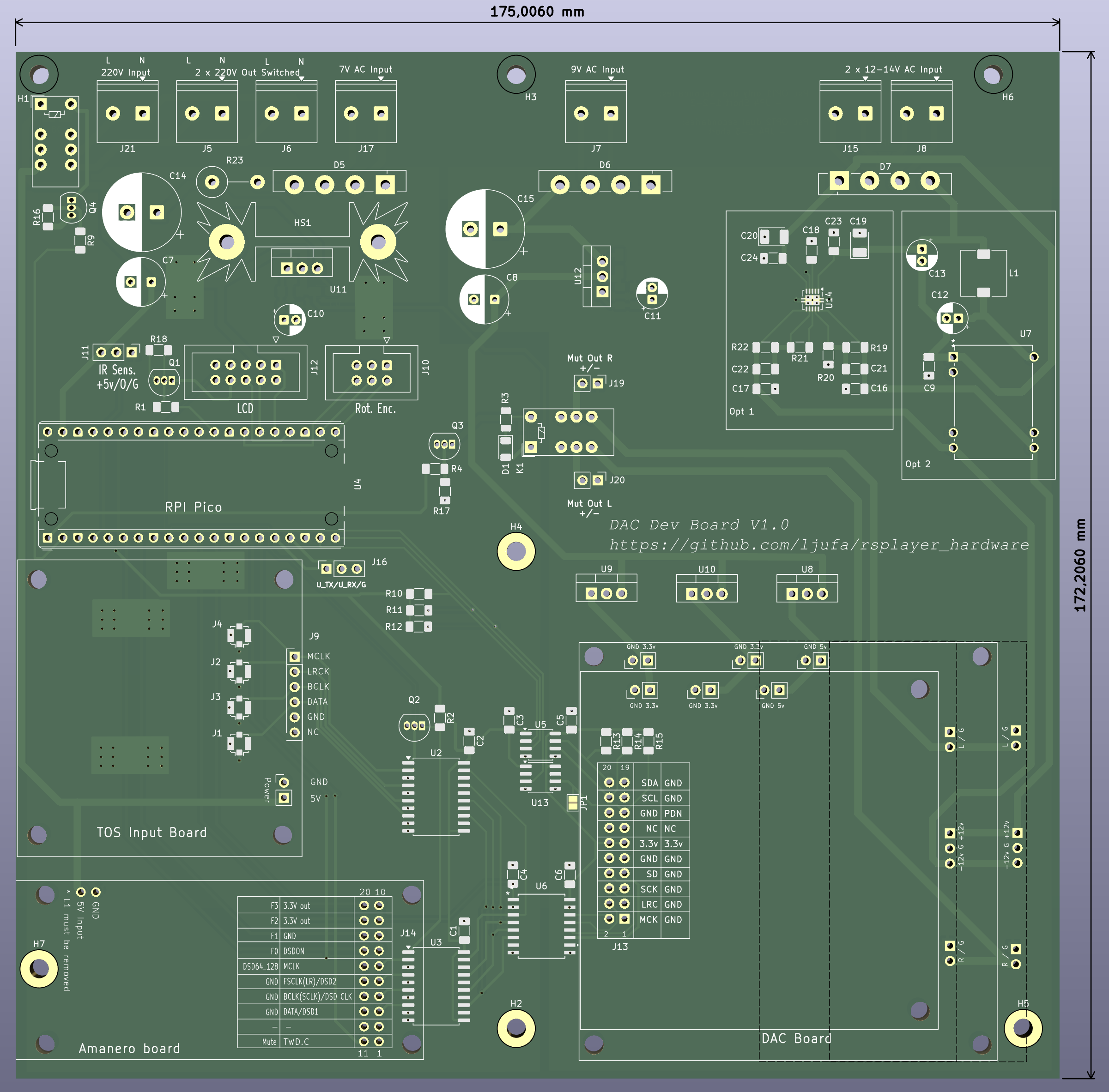
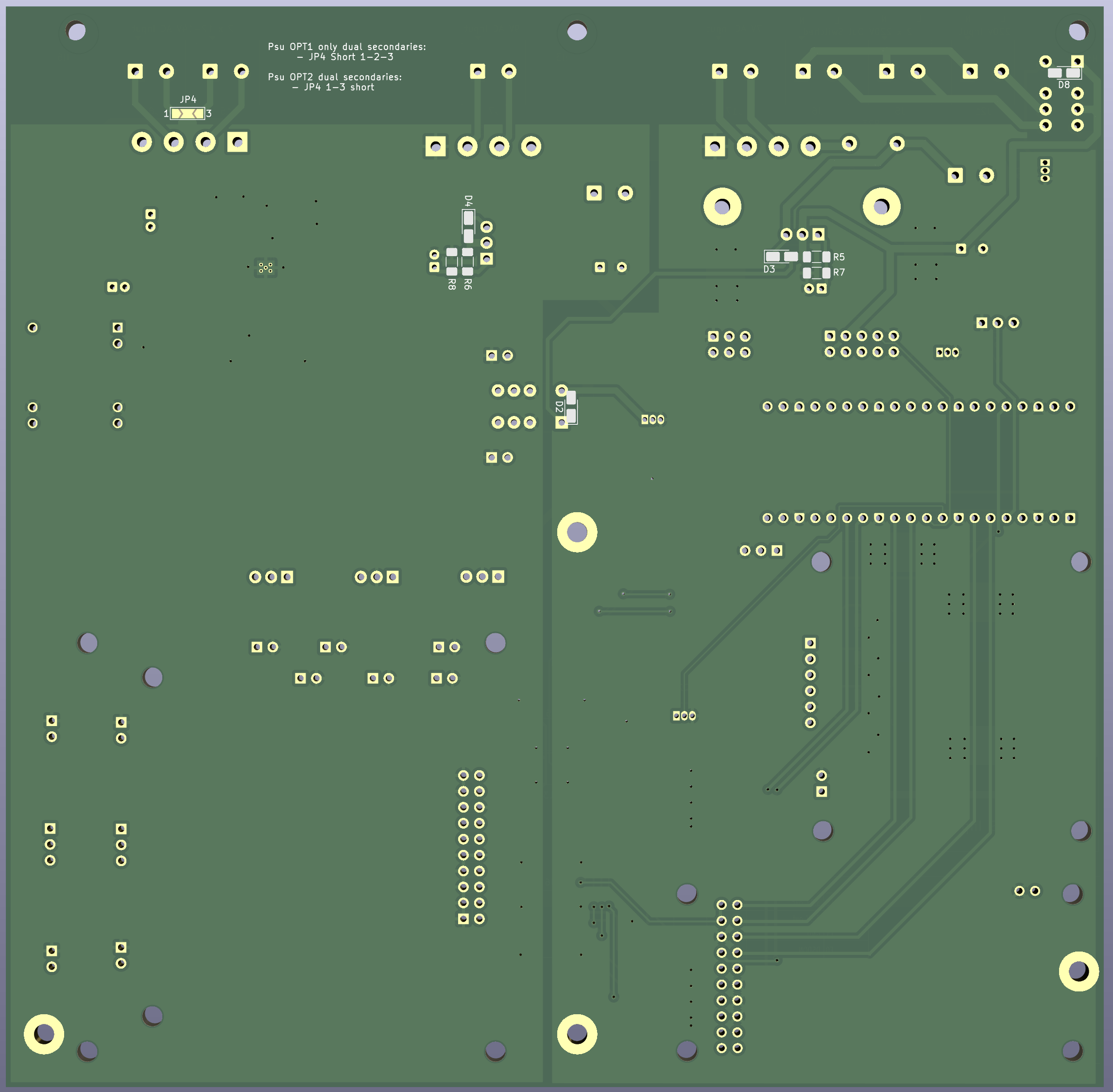
Control board is an open-source printed circuit board by ljufa, from the ljufa/rsplayer_hardware repository on GitHub, published under the MIT licence. It is a 2-layer board of 175 × 172.2 mm with 105 parts on 124 nets, routed with 679 tracks and 108 vias.
It is built around the 74AC573PC, ADUM1250AR and IL715E, with the BC547 and BS170 among its other parts. Its parts include 24 capacitors, 23 resistors, 20 connectors, 13 ICs and 8 diodes. It belongs with the RP2040 boards of this library.


This repository contains the hardware design files for the RSPlayer project, a high-quality audio player. The designs are created in KiCad.
This hardware design prioritizes modularity and DIY-friendliness. The goal is to provide a flexible platform where enthusiasts can easily swap components, upgrade specific subsystems (like power regulators or output stages), and experiment with different configurations. This open architecture encourages users to tweak the design, test new ideas, and continuously improve the audio performance to match their personal preferences.
This repository is structured into several directories, each containing a specific board or a set of related files:
dual and dual_mono configurations.LT3045_breakout design) acting as high-performance drop-in replacements for standard regulators, providing industry-leading low noise (0.8µVrms) and ultra-high PSRR.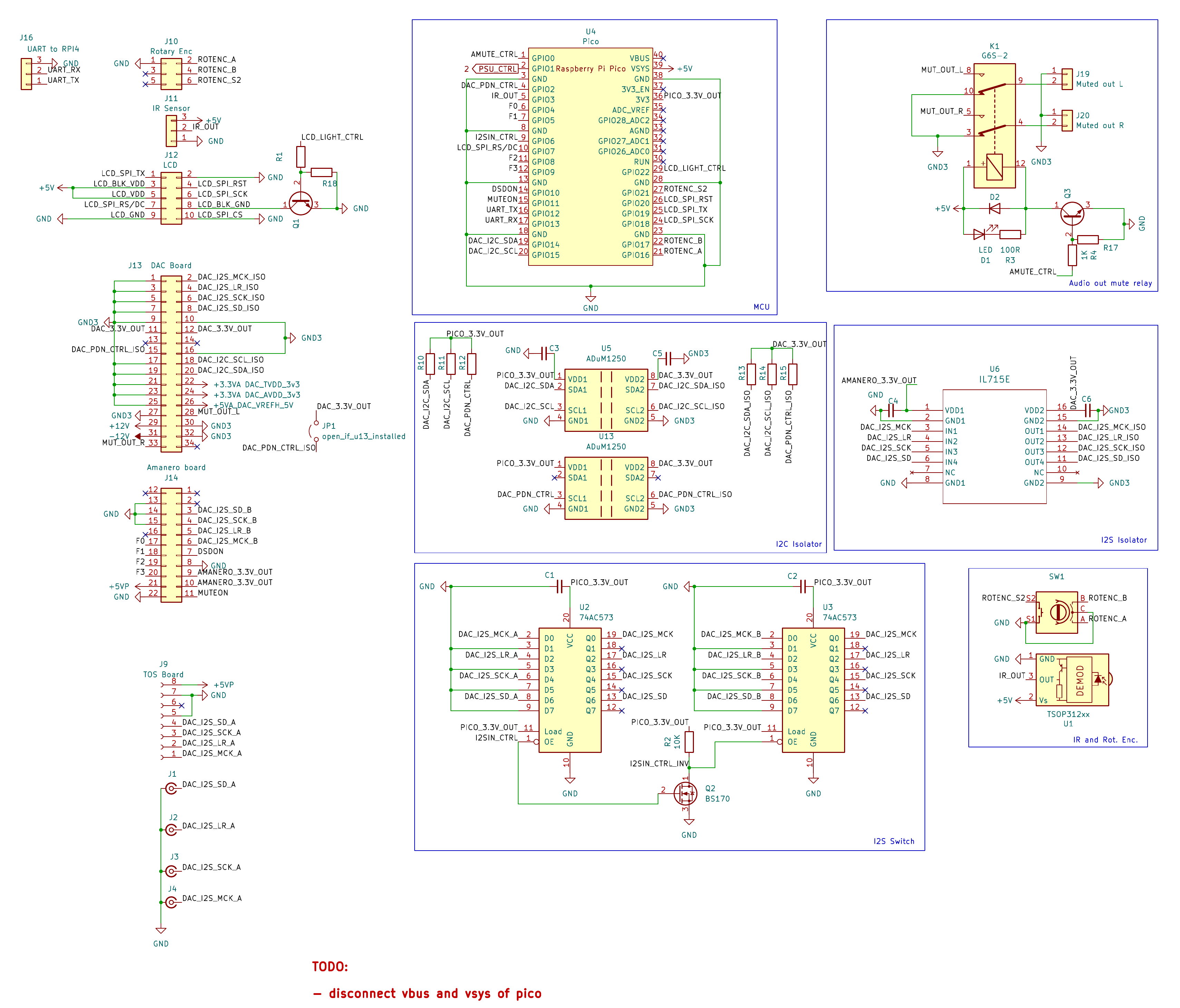
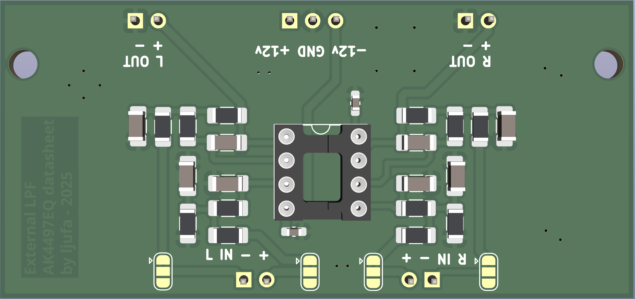
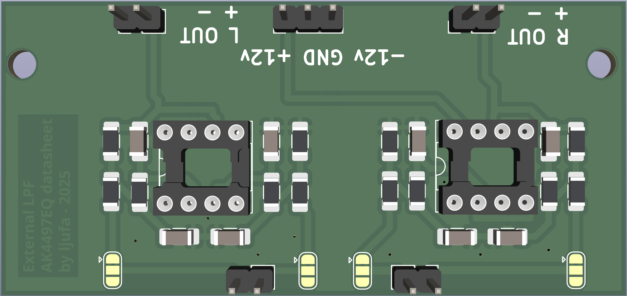
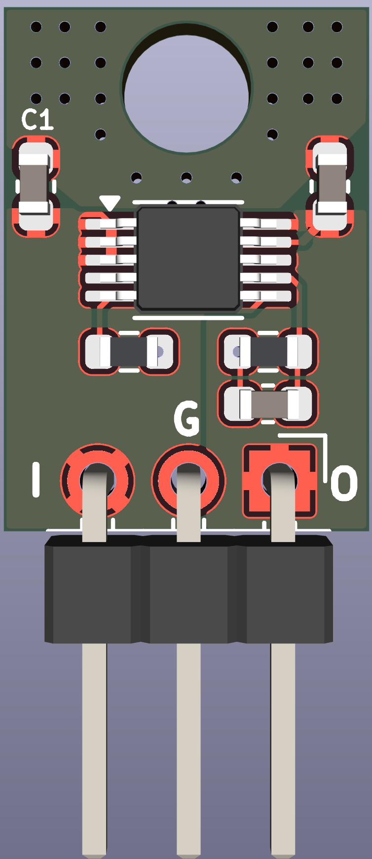
The project is evolving to become a universal high-fidelity audio platform. Planned improvements include:
The RSPlayer is a multi-repository project:
This project is licensed under the MIT License. See the LICENSE file for details.
| Qty | Value | Footprint | References |
|---|---|---|---|
| 10 | 0.1u | Capacitor_SMD:C_1206_3216Metric_Pad1.33x1.80mm_HandSolder | C1, C2, C3, C4, C5, C6, C21, C22, C23, C24 |
| 10 | 10K | Resistor_SMD:R_1206_3216Metric_Pad1.30x1.75mm_HandSolder | R2, R10, R11, R12, R13, R14, R15, R16, R17, R18 |
| 4 | 10uF | Capacitor_THT:CP_Radial_D5.0mm_P2.00mm | C10, C11, C12, C13 |
| 4 | 1N4004 | Diode_SMD:D_MicroMELF_Handsoldering | D2, D3, D4, D8 |
| 4 | Conn_Coaxial_Small | Connector_Coaxial:U.FL_Molex_MCRF_73412-0110_Vertical | J1, J2, J3, J4 |
| 4 | SEC | TerminalBlock_Philmore:TerminalBlock_Philmore_TB132_1x02_P5.00mm_Horizontal | J7, J8, J15, J17 |
| 4 | ~ | MountingHole:MountingHole_3.2mm_M3_Pad_TopBottom | H2, H4, H5, H7 |
| 3 | 1K | Resistor_SMD:R_1206_3216Metric_Pad1.30x1.75mm_HandSolder | R1, R4, R9 |
| 3 | 220vac | TerminalBlock_Philmore:TerminalBlock_Philmore_TB132_1x02_P5.00mm_Horizontal | J5, J6, J21 |
| 3 | B80C3x00-2200A | Diode_THT:Diode_Bridge_Vishay_GBU | D5, D6, D7 |
| 3 | BC547 | Package_TO_SOT_THT:TO-92_Inline | Q1, Q3, Q4 |
| 3 | lt3042_breakout | Package_TO_SOT_THT:TO-220-3_Vertical | U8, U9, U10 |
| 3 | ~ | MountingHole:MountingHole_3.2mm_M3 | H1, H3, H6 |
| 2 | 100R | Resistor_SMD:R_1206_3216Metric_Pad1.30x1.75mm_HandSolder | R5, R6 |
| 2 | 100uF | Capacitor_THT:CP_Radial_D8.0mm_P3.50mm | C7, C8 |
| 2 | 10k | Resistor_SMD:R_1206_3216Metric_Pad1.30x1.75mm_HandSolder | R20, R21 |
| 2 | 470uF | Capacitor_THT:CP_Radial_D13.0mm_P5.00mm | C14, C15 |
| 2 | 74AC573 | Package_SO:SOIC-20W_7.5x12.8mm_P1.27mm | U2, U3 |
| 2 | ADuM1250 | Package_SO:SOIC-8_3.9x4.9mm_P1.27mm | U5, U13 |
| 2 | G6S-2 | Relay_THT:Relay_DPDT_Omron_G6S-2 | K1, K2 |
| 2 | LT1084-ADJ | Package_TO_SOT_THT:TO-220-3_Vertical | U11, U12 |
| 2 | Value=22uF | Capacitor_SMD:C_1206_3216Metric_Pad1.33x1.80mm_HandSolder | C16, C17 |
| 2 | Value=33uF Rser=350m | Capacitor_Tantalum_SMD:CP_EIA-3528-21_Kemet-B_HandSolder | C19, C20 |
| 1 | 0R | Resistor_THT:R_Axial_DIN0516_L15.5mm_D5.0mm_P7.62mm_Vertical | R23 |
| 1 | 100R | Resistor_SMD:R_1206_3216Metric | R3 |
| 1 | 100k | Resistor_SMD:R_1206_3216Metric_Pad1.30x1.75mm_HandSolder | R22 |
| 1 | 220pF | Capacitor_SMD:C_1206_3216Metric_Pad1.33x1.80mm_HandSolder | C9 |
| 1 | 300R | Resistor_SMD:R_1206_3216Metric_Pad1.30x1.75mm_HandSolder | R7 |
| 1 | 470R | Resistor_SMD:R_1206_3216Metric_Pad1.30x1.75mm_HandSolder | R8 |
| 1 | 8.2uH | Inductor_SMD:L_SXN_SMDRI73 | L1 |
| 1 | 90.9K | Resistor_SMD:R_1206_3216Metric_Pad1.30x1.75mm_HandSolder | R19 |
| 1 | Amanero board | MyLibrary:Amanero Combo768 | J14 |
| 1 | BS170 | Package_TO_SOT_THT:TO-92_Inline | Q2 |
| 1 | DAC Board | MyLibrary:diyinkhak4490+4497board | J13 |
| 1 | Heatsink | Heatsink:Heatsink_Fischer_SK104-STC-STIC_35x13mm_2xDrill2.5mm | HS1 |
| 1 | IL715E | MyLibrary:SOIC16_WIDE_NVE | U6 |
| 1 | IR Sensor | Connector_PinHeader_2.54mm:PinHeader_1x03_P2.54mm_Vertical | J11 |
| 1 | LCD | Connector_IDC:IDC-Header_2x05_P2.54mm_Vertical | J12 |
| 1 | LED | LED_SMD:LED_1206_3216Metric | D1 |
| 1 | Muted out L | Connector_PinHeader_2.54mm:PinHeader_1x02_P2.54mm_Vertical | J19 |
| 1 | Muted out R | Connector_PinHeader_2.54mm:PinHeader_1x02_P2.54mm_Vertical | J20 |
| 1 | Pico | MyLibrary:RaspberryPi_Pico_Common_THT | U4 |
| 1 | Rotary Enc | Connector_IDC:IDC-Header_2x03_P2.54mm_Vertical | J10 |
| 1 | SolderJumper_3_Open | Jumper:SolderJumper-3_P2.0mm_Open_TrianglePad1.0x1.5mm_NumberLabels | JP4 |
| 1 | TDR 2-2422 | MyLibrary:TDR 2 DUAL_TRP | U7 |
| 1 | TOS Board | MyLibrary:tosInputBoard | J9 |
| 1 | TPS7A39 | Package_SON:Texas_S-PVSON-N10_ThermalVias | U14 |
| 1 | UART to RPI4 | Connector_PinSocket_2.54mm:PinSocket_1x03_P2.54mm_Vertical | J16 |
| 1 | Value=10nF | Capacitor_SMD:C_1206_3216Metric_Pad1.33x1.80mm_HandSolder | C18 |
| 1 | open_if_u13_installed | Jumper:SolderJumper-2_P1.3mm_Open_Pad1.0x1.5mm | JP1 |
ljufa/rsplayer_hardware
kicad files for rsplayer music player hardware

ljufa/rsplayer_hardware
kicad files for rsplayer music player hardware


46nori/Z80Atmega128
Real Z80A system with I/O emulated by AVR(ATmega128)


ja1umi/MUTIF09Project
Various design materials for building my 8-bit-microprocessor-based single board computer(s)
It measures 175 × 172.2 mm and has 2 copper layers, 1.6 mm thick.
105 parts, built around the 74AC573PC, ADUM1250AR, IL715E and BC547. The full list of its parts is on this page, with links to each part's symbol and footprint where PCBKit's library has them.
From the ljufa/rsplayer_hardware repository on GitHub, at the commit this page was made from: the board is control_board_with_amanero/control_board.kicad_pcb and its schematic LT3042_breakout/LT3042_breakout.kicad_sch. PCBKit opens the board in the browser, with nothing to install.
Its repository publishes it under the MIT licence: you may reuse it on that licence's terms (keep the author's notice, and for a copyleft licence share your changes alike).