4 layers40.6 × 17.8 mm

 c0pperdragon/OS81628
An experimental single-board computer using the 65C816
OS816 is an open-source printed circuit board by c0pperdragon, from the c0pperdragon/OS816 repository on GitHub. It is a 4-layer board of 76.7 × 76.7 mm with 40 parts on 84 nets, routed with 1,153 tracks and 106 vias.
It is built around the 74HC245D, 74AC573PC and 74HC04D, with the 74HC138 and 74HC574D among its other parts. Its parts include 8 capacitors, 8 ICs, 8 diodes, 4 resistors and 1 crystal. It belongs with the computers and single-board computers boards of this library.


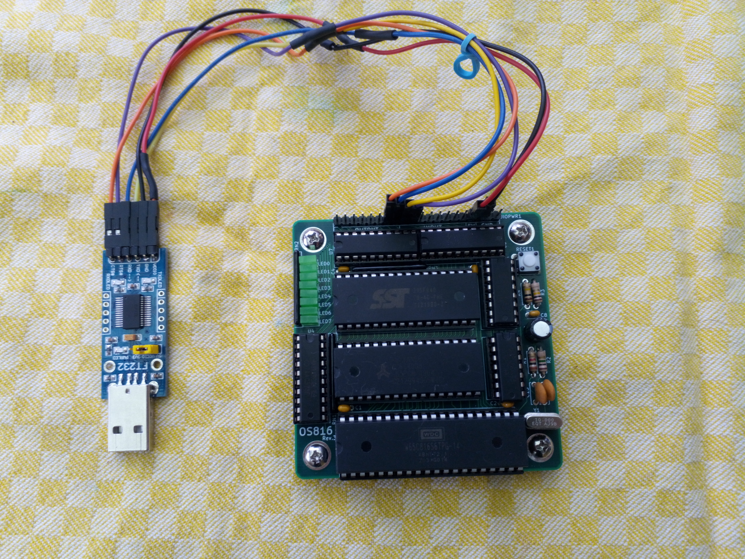
A small single board computer using the 65C816 processor running at 10MHz, together with 512KB of RAM, 512KB of flash and a simple but effective I/O circuitry.
I made a small boot loader program for this hardware sitting in the top 4KB of flash to upload further code via a serial connection to avoid the need of swapping the Flash IC in and out of the board all the time.
User programs can be developed with the WDC compiler tool chain that provides an assembler as well as a C compiler confirming to the C89/90 standard (a.k.a ANSI C). I had to fix some bugs and add implementations for stdin/stdout over serial and file access to utilize the unoccupied area of the Flash memory. By now it is complete enough to run the "frotz" interactive fiction interpreter to play some of the old text adventure classics.
This processor is a tricky beast to use in a circuit as it has some unusual quirks that need consideration, especially when you want to use more than 64KB of address space.
Points 1 and 2 are just solved with some extra logic on the board. Point 3 is solved by using the emulation bit to force the top 8 address lines to $FF during startup time. Once the program is running it switches to native mode to make use of the full address range with flat regions for both RAM, IO and flash.
| from | to | type |
|---|---|---|
| 000000 | 07FFFF | RAM |
| 400000 | 400000 | IO port |
| C00000 | C7EFFF | User flash |
| FFF000 | FFFFFF | Boot loader flash |
Many other ranges of the 16MB space are mirrors of some of the specified ranges here, but should not be used in order to allow future extensions.
The free WDC compiler tools (running on Windows only) are used that include a C compiler, so it is easy to get most things done without directly touching the 65C816 machine code. The OS816 libraries are designed for the "large" memory model to evenly access static and dynamic data without bothering about banks, direct page and all the other intricate details of this specific CPU. Low level access to the hardware (essentially to the IO port, but also the flash programming functions) is provided by libraries that are directly written in machine code for best performance and because sometimes it would not be possible otherwise.
The necessary compiler and linker can be found at the Western Design Center's download page. Additionally you need a python 3 interpreter to run my extra build tools.
To see how all these tools should be used, have a look at the build scripts for the various examples provided.
This is a step you probably need to do only once, but it requires the use of a dedicated chip programmer, like the TL866-II Plus and its corresponding programming software. Building the OS816 libraries by executing the 'build.bat' script in the 'src' directory, will create some libraries in the 'bin' directory, and also the 'boot.hex' file which needs to be written to the flash IC. To avoid buying this not completely cheap programmer I could provide you with a pre-flashed IC for a reasonable price.
With the kit I sell at tindie, the flash IC comes already pre-programmed.
With its simple IO hardware, the CPU is in charge of all signal handling. With a 10MHz clock and hand-crafted machine code it was possible to implement a reliable serial communication that can run at 115.2kHz (1 start bit, 1 stop bit, no parity). But as the CPU can not do any communication when being busy with other things it is necessary that the communication partner must only send data when the CPU is prepared to receive it. A straight forward solution is the use of hardware flow control using RTS/CTS handshake lines. In my reference setup I use a cheap USB-to-UART interface board with support for these signals.
| Pin location | OS816 | Partner |
|---|---|---|
| OUTPUT 0 | TX | RX |
| OUTPUT 1 | RTS | CTS |
| INPUT 7 | RX | TX |
| INPUT 6 | CTS | RTS |
If your USB-to-UART interface does only have a CTS input, but no RTS output, this can also be made to work. Just pull the CTS input of the OS816 permanently to GND to disable flow control in the direction from the OS816 to your computer, assuming that your computer is fast enough so it can always process all incomming data.
Compiling with the recommended tools will create a file in Intel HEX format. This file contains the "user code" which can be written to flash using the resident boot loader program. When starting up the machine with a serial terminal attached, the boot loader enters a command line interface. Here memory locations can be inspected or modified and also the content of the flash can be reprogrammed. After completely erasing the user flash area with the "!" command, you can conveniently dump a whole intel hex file into the terminal whose lines will be treated as individual programming commands. Once the user program is in the flash, the command "x" will start up this program. When the machine starts up with a user program already installed, the boot loader will give you 1 second time to enter the command line interface by pressing a key. Otherwise it will fire up the user program directly.
I have chosen this moderately fast 10MHz as the clock speed to always stay safely inside all the timing constraints and to make cycle-counting as simple as possible. But I was also able to run the board at 16MHz without problems. If you want to try this, you need to swap out the crystal and set the serial communication speed in your terminal program accordingly.
For questions regarding purchases of either a pre-programmed flash IC or a whole kit for self-assembly (using through-hole parts exclusively), please contact me directly at: reinhard.grafl (at) aon.at
For other questions that may also be of interest for other users, please create an issue ticket.
| Qty | Value | Footprint | References |
|---|---|---|---|
| 8 | LED_Small | LED_THT:LED_D2.0mm_W4.8mm_H2.5mm_FlatTop | LED0, LED1, LED2, LED3, LED4, LED5, LED6, LED7 |
| 4 | 100nF | Capacitor_THT:C_Disc_D3.0mm_W2.0mm_P2.50mm | C1, C2, C3, C4 |
| 2 | 10k | Resistor_THT:R_Array_SIP9 | RN1, RN3 |
| 2 | 10k | Resistor_THT:R_Axial_DIN0207_L6.3mm_D2.5mm_P7.62mm_Horizontal | R3, R4 |
| 2 | 33pF | Capacitor_THT:C_Disc_D6.0mm_W2.5mm_P5.00mm | C12, C13 |
| 1 | 100uF | Capacitor_THT:CP_Radial_D5.0mm_P2.50mm | C11 |
| 1 | 10MHz | Crystal:Resonator-2Pin_W7.0mm_H2.5mm | Y1 |
| 1 | 1M | Resistor_THT:R_Axial_DIN0207_L6.3mm_D2.5mm_P7.62mm_Horizontal | R2 |
| 1 | 1k | Resistor_THT:R_Axial_DIN0207_L6.3mm_D2.5mm_P7.62mm_Horizontal | R1 |
| 1 | 1k | Resistor_THT:R_Array_SIP9 | RN2 |
| 1 | 1uF | Capacitor_THT:C_Disc_D3.0mm_W2.0mm_P2.50mm | C8 |
| 1 | 65C816 | Package_DIP:DIP-40_W15.24mm_Socket | U1 |
| 1 | 74AC573 | Package_DIP:DIP-20_W7.62mm_Socket | U4 |
| 1 | 74HC04 | Package_DIP:DIP-14_W7.62mm_Socket | U5 |
| 1 | 74HC138 | Package_DIP:DIP-16_W7.62mm_Socket | U6 |
| 1 | 74HC245 | Package_DIP:DIP-20_W7.62mm_Socket | U8 |
| 1 | 74HC574 | Package_DIP:DIP-20_W7.62mm_Socket | U7 |
| 1 | AS6C4008 | Package_DIP:DIP-32_W15.24mm_Socket | U2 |
| 1 | Conn_01x03 | Connector_PinSocket_2.54mm:PinSocket_1x03_P2.54mm_Vertical | JADR1 |
| 1 | Conn_01x20 | Connector_PinSocket_2.54mm:PinSocket_1x20_P2.54mm_Vertical | JAUX1 |
| 1 | Conn_01x20_Male | Connector_PinHeader_2.54mm:PinHeader_1x20_P2.54mm_Vertical | JIOPWR1 |
| 1 | SST39SF040 | Package_DIP:DIP-32_W15.24mm_Socket | U3 |
| 1 | SW_Push | Button_Switch_THT:SW_PUSH_6mm_H4.3mm | RESET1 |
The 36 most common of 40 parts.


c0pperdragon/BreadBin
A CPU made of 7400 logic on breadboards - inside a bread bin ;-)


It measures 76.7 × 76.7 mm and has 4 copper layers, 1.6 mm thick.
40 parts, built around the 74HC245D, 74AC573PC, 74HC04D and 74HC138. The full list of its parts is on this page, with links to each part's symbol and footprint where PCBKit's library has them.
From the c0pperdragon/OS816 repository on GitHub, at the commit this page was made from: the board is mainboard/mainboard.kicad_pcb and its schematic mainboard/mainboard.kicad_sch. PCBKit opens the board in the browser, with nothing to install.
Its repository states no licence, so its author keeps all rights: ask c0pperdragon before reusing the design.