2 layers119 × 47.5 mm

 legowoo/8-DI-ESP32-PCB1
A printed circuit board that enables a ESP32 to interface with digital inputs up to 28VDC.
8-DI ESP32-PCB is an open-source printed circuit board by legowoo, from the legowoo/8-DI-ESP32-PCB repository on GitHub, published under the GPL-3.0 licence. It is a 4-layer board of 100 × 72 mm with 67 parts on 39 nets, routed with 350 tracks and 141 vias.
It is built around the ESP32-WROVER-IE and LTV-247. Its parts include 19 resistors, 15 capacitors, 12 diodes, 11 connectors and 4 ICs. It belongs with the ESP32 and RISC-V boards of this library.

A printed circuit board that enables a ESP32 to interface with digital inputs up to 28VDC.
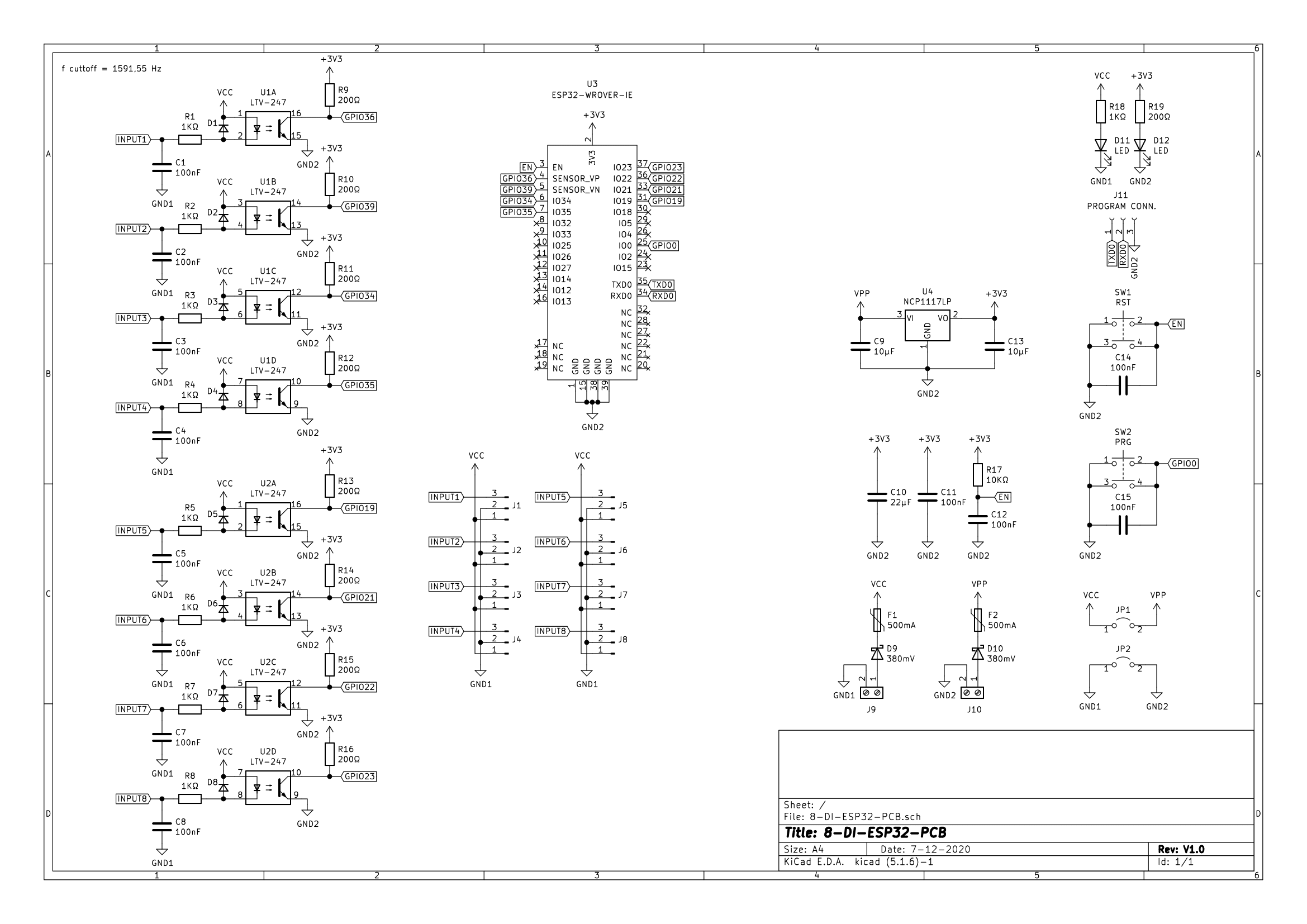
J9: Screw terminal for supplying voltage to the sensors that are connected to the optocouplers. Input voltage range: 5-24VDC
J10: Screw terminal for supplying voltage to the ESP itself. Input voltage range: 5-12VDC
D11: Led to indicate the presents/absent of a voltage on the VCC rail (J9).
D12: Led to indicate the presents/absent of the +3V3 rail (J10).
JP1: Jumper to connect the VCC to VPP. Used to remove the Galvanic isolation between the sensors and ESP.
Only populate this jumper if one voltage source is being used!
JP2: Jumper to connect GND1 to GND2. Used to remove the Galvanic isolation between the sensors and ESP.
J1-J8: Each digital input has its own header connected to the ESP. Pinout from left to right: 1=VCC, 2=GND and 3=GPIO
SW1: Resart the ESP
SW2: put the ESP in program mode if the ESP is booting
J11: Program connector. Connect any +3V3 UART programmer to write a program to the ESP.
note: the ESP needs to be manualy set to program mode via SW1 and SW2.
| Qty | Value | Footprint | References |
|---|---|---|---|
| 12 | 100nF | Capacitor_SMD:C_0805_2012Metric_Pad1.15x1.40mm_HandSolder | C1, C2, C3, C4, C5, C6, C7, C8, C11, C12, C14, C15 |
| 9 | 1KΩ | Resistor_SMD:R_1206_3216Metric_Pad1.42x1.75mm_HandSolder | R1, R2, R3, R4, R5, R6, R7, R8, R18 |
| 9 | 200Ω | Resistor_SMD:R_1206_3216Metric_Pad1.42x1.75mm_HandSolder | R9, R10, R11, R12, R13, R14, R15, R16, R19 |
| 8 | Conn_01x03_Male | Custom Library:CUI_TBP02R2-381-03BE | J1, J2, J3, J4, J5, J6, J7, J8 |
| 8 | D_ESD | Diode_SMD:D_SOD-323_HandSoldering | D1, D2, D3, D4, D5, D6, D7, D8 |
| 2 | 10µF | Capacitor_SMD:C_Elec_5x5.4 | C9, C13 |
| 2 | 380mV | Diode_SMD:D_SOD-123F | D9, D10 |
| 2 | 500mA | Fuse:Fuse_1206_3216Metric_Pad1.42x1.75mm_HandSolder | F1, F2 |
| 2 | Jumper_2_Open | Connector_PinHeader_2.54mm:PinHeader_1x02_P2.54mm_Vertical | JP1, JP2 |
| 2 | LED | LED_SMD:LED_1206_3216Metric | D11, D12 |
| 2 | LTV-247 | Package_SO:SOP-16_4.4x10.4mm_P1.27mm | U1, U2 |
| 2 | Screw_Terminal_01x02 | Custom Library:CUI_TB004-508-02BE | J9, J10 |
| 1 | 10KΩ | Resistor_SMD:R_1206_3216Metric_Pad1.42x1.75mm_HandSolder | R17 |
| 1 | 22µF | Capacitor_SMD:C_Elec_6.3x5.4 | C10 |
| 1 | ESP32-WROVER-IE | Custom Library:ESP32-WROVER-IE | U3 |
| 1 | NCP1117LP | Package_TO_SOT_SMD:SOT-223-3_TabPin2 | U4 |
| 1 | PRG | Custom Library:PTS647SM38SMTR2LFS | SW2 |
| 1 | PROGRAM CONN. | Connector_PinSocket_2.54mm:PinSocket_1x03_P2.54mm_Vertical | J11 |
| 1 | RST | Custom Library:PTS647SM38SMTR2LFS | SW1 |

RomLab/pcb-system-for-underfloor-heating-v2.0
PCB for underfloor heating system


ADVecu/CANBoard-Carrier
An automotive-grade carrier board for the CANBoard-HW. This board adapts the system for reliable use in vehicles and motorcycles.


icl-rocketry/Ricardo-PickleRick
A more compact Ricardo classic featuring a new sensor array, 4 pyro channels and 4 servo channels. Includes Ricardo bus plug too.

It measures 100 × 72 mm and has 4 copper layers, 1.6 mm thick.
67 parts, built around the ESP32-WROVER-IE and LTV-247. The full list of its parts is on this page, with links to each part's symbol and footprint where PCBKit's library has them.
From the legowoo/8-DI-ESP32-PCB repository on GitHub, at the commit this page was made from: the board is 8-DI-ESP32-PCB.kicad_pcb. PCBKit opens the board in the browser, with nothing to install.
Its repository publishes it under the GPL-3.0 licence: you may reuse it on that licence's terms (keep the author's notice, and for a copyleft licence share your changes alike).