4 layers62.2 × 73.8 mm

 ADVecu/CANBoard-Carrier4
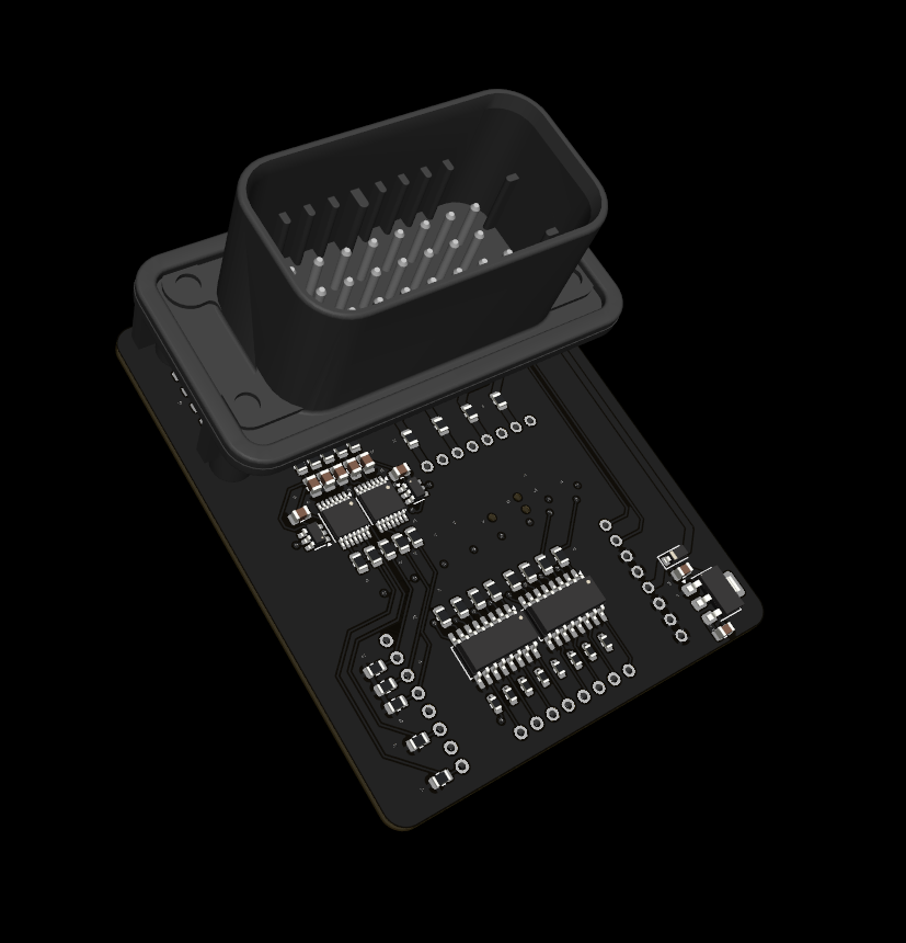
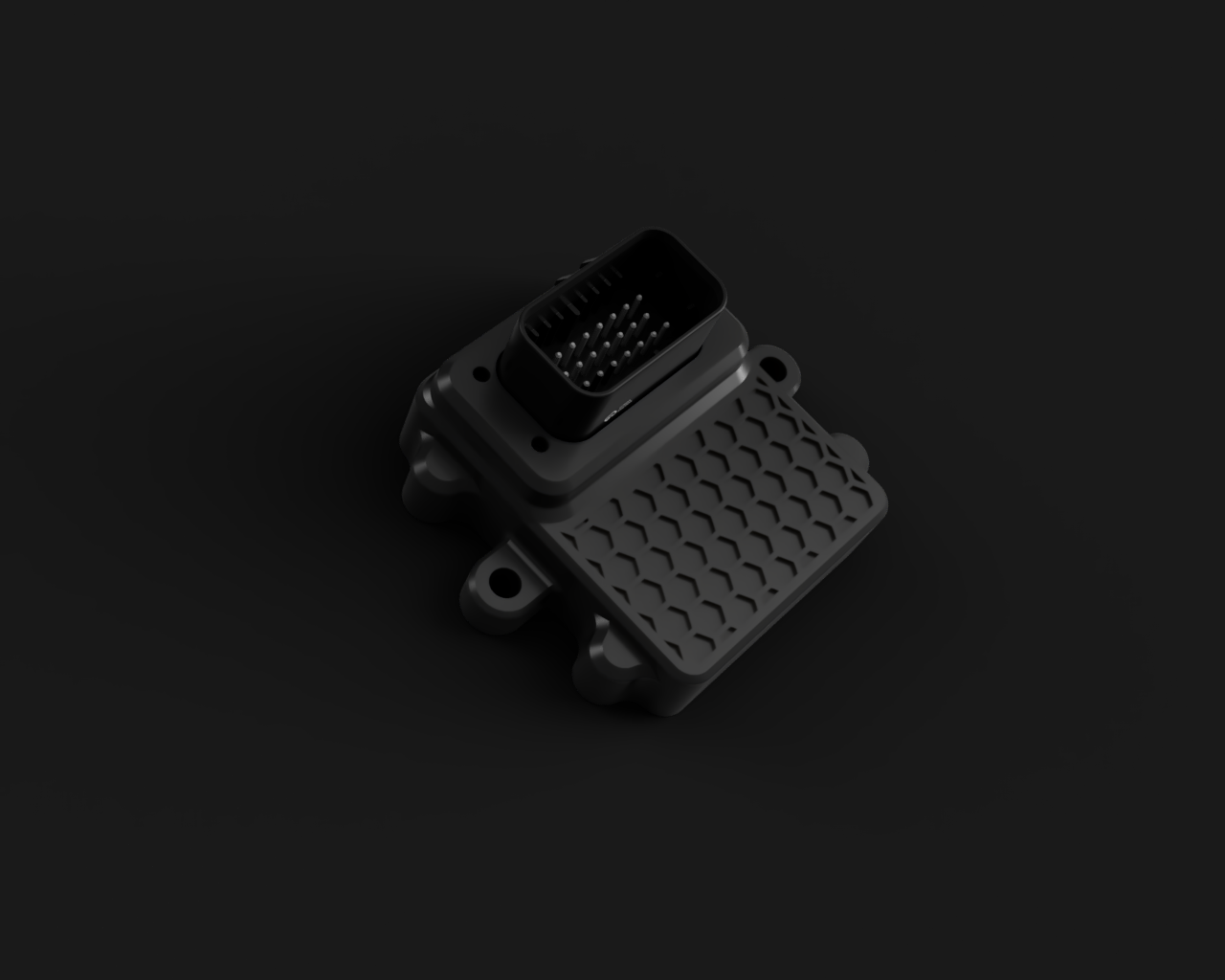
An automotive-grade carrier board for the CANBoard-HW. This board adapts the system for reliable use in vehicles and motorcycles.
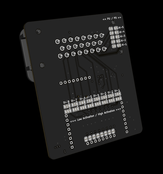
CANBoard Base is an open-source printed circuit board by ADVecu, from the ADVecu/CANBoard-Carrier repository on GitHub. It is a 4-layer board of 62 × 75 mm with 100 parts on 102 nets, routed with 569 tracks and 113 vias.
It is built around the MCP6004-E/P, LTV-247 and SRV05-4, with the LD1117S33CTR-HXY among its other parts. Its parts include 41 resistors, 9 capacitors, 8 ICs, 5 fuses and 2 diodes.


An automotive-grade carrier board for the CANBoard-HW. This board adapts the system for reliable use in vehicles and motorcycles.
| Pin | Label | Function |
|---|---|---|
| 1 | +12V | Main Power Input (via Schottky D2) |
| 2 | GND | System Ground |
| 3 | CANL | CAN Bus Low |
| 4 | CANH | CAN Bus High |
| 5 | +5VP | Protected 5V Output / Sensor Power |
| 6 | GND | System Ground |
| 7 | DO1 | Digital Output 1 |
| 8 | DO2 | Digital Output 2 |
| 9 | AI5_RAW | Analog Input 5 |
| 10 | AI1_RAW | Analog Input 1 |
| 11 | DI1_RAW | Digital Input 1 (Opto-isolated) |
| 12 | DI3_RAW | Digital Input 3 (Opto-isolated) |
| 13 | DI5_RAW | Digital Input 5 (Opto-isolated) |
| 14 | DI7_RAW | Digital Input 7 (Opto-isolated) |
| 15 | DO3 | Digital Output 3 |
| 16 | AI4_RAW | Analog Input 4 |
| 17 | AI3_RAW | Analog Input 3 |
| 18 | AI2_RAW | Analog Input 2 |
| 19 | DI2_RAW | Digital Input 2 (Opto-isolated) |
| 20 | DI4_RAW | Digital Input 4 (Opto-isolated) |
| 21 | DI6_RAW | Digital Input 6 (Opto-isolated) |
| 22 | DI8_RAW | Digital Input 8 (Opto-isolated) |
| 23 | DO4 | Digital Output 4 |
This project is based on CANBoard-Base for use with Cory Grant's CANBoard-HW.
| Qty | Value | Footprint | References |
|---|---|---|---|
| 18 | SolderJumper_2_Open | Jumper:SolderJumper-2_P1.3mm_Open_RoundedPad1.0x1.5mm | JP2, JP11, JP14, JP17, JP20, JP23, JP25, JP26, JP27, JP28, JP29, JP30, JP31, JP32, JP33, JP34 +2 |
| 16 | SolderJumper_3_Open | Jumper:SolderJumper-3_P1.3mm_Open_Pad1.0x1.5mm | JP1, JP3, JP4, JP6, JP7, JP9, JP10, JP12, JP13, JP15, JP16, JP18, JP19, JP21, JP22, JP24 |
| 10 | 10K | Resistor_SMD:R_0805_2012Metric | R25, R26, R27, R28, R29, R30, R32, R33, R35, R37 |
| 8 | 100nF | Capacitor_SMD:C_0805_2012Metric | C1, C3, C4, C5, C6, C7, C8, C9 |
| 8 | 2.7k | Resistor_SMD:R_0603_1608Metric | R1, R3, R5, R7, R9, R11, R13, R15 |
| 8 | 2k7 | Resistor_SMD:R_0805_2012Metric | R2, R4, R6, R8, R10, R12, R14, R16 |
| 5 | 0.5A | Fuse:Fuse_0805_2012Metric | F1, F2, F3, F4, F5 |
| 5 | 2.7K | Resistor_SMD:R_0805_2012Metric | R17, R18, R20, R21, R22 |
| 5 | 4.7K | Resistor_SMD:R_0805_2012Metric | R19, R23, R24, R31, R34 |
| 5 | 470K | Resistor_SMD:R_0805_2012Metric | R36, R38, R39, R40, R41 |
| 2 | LTV-247 | Package_SO:SOP-16_4.4x10.4mm_P1.27mm | U3, U4 |
| 2 | MCP6004 | Package_SO:TSSOP-14_4.4x5mm_P0.65mm | U5, U6 |
| 2 | SRV05-4 | Package_TO_SOT_SMD:SOT-23-6 | U7, U8 |
| 2 | Schottky | Diode_SMD:D_SOD-123 | D1, D2 |
| 1 | 10uF | Capacitor_SMD:C_0805_2012Metric | C2 |
| 1 | 776228-1 | easyeda2kicad:CONN-TH_776228-1 | CN1 |
| 1 | CANBoard_v2 | CANBoard:CANBoard_v2_NoMountingHoles_TagConnectHoles | U2 |
| 1 | LD1117S33CTR | Package_TO_SOT_SMD:SOT-223 | U1 |

rusefi/hw_microRusEfi
microRusEfi board for rusEfi ECU


halbritt/fome-mc
FOME-MC integrated single-PCB motorcycle ECU (STM32H753 + 2x STM32F042 WBO)

eauel/openzmeter
openzmeter (oZm) is an Open Source system designed for power quality analysis and smart energy metering in power networks. It has been designed to comply with international standards IEC 61000-4-30 and EN 50160.
It measures 62 × 75 mm and has 4 copper layers, 1.6 mm thick.
100 parts, built around the MCP6004-E/P, LTV-247, SRV05-4 and LD1117S33CTR-HXY. The full list of its parts is on this page, with links to each part's symbol and footprint where PCBKit's library has them.
From the ADVecu/CANBoard-Carrier repository on GitHub, at the commit this page was made from: the board is CANBoard-Base/CANBoard-Base.kicad_pcb and its schematic CANBoard-Base/AnalogInputs.kicad_sch. PCBKit opens the board in the browser, with nothing to install.
Its repository states no licence, so its author keeps all rights: ask ADVecu before reusing the design.