2 layers217.2 × 113 mm
Junior computer
laurent-fr/junior_computer_replica
A replica of the Junior Computer (a KIM-1 clone) published by Elektor in the 80's
86 parts14

 laurent-fr/junior_computer_replica14
A replica of the Junior Computer (a KIM-1 clone) published by Elektor in the 80's
Junior interface is an open-source printed circuit board by laurent-fr, from the laurent-fr/junior_computer_replica repository on GitHub. It is a 2-layer board of 217.2 × 113 mm with 120 parts on 213 nets, routed with 2,982 tracks and 38 vias.
It is built around the 74LS241P-E, LM311 and 74LS00SC, with the 74LS27P-E, 74LS30PC and BC516 among its other parts. Its parts include 37 resistors, 32 connectors, 22 capacitors, 17 ICs and 3 diodes. It belongs with the interfaces and adapters boards and the FPGA and CPLD boards of this library.


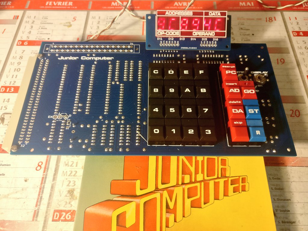
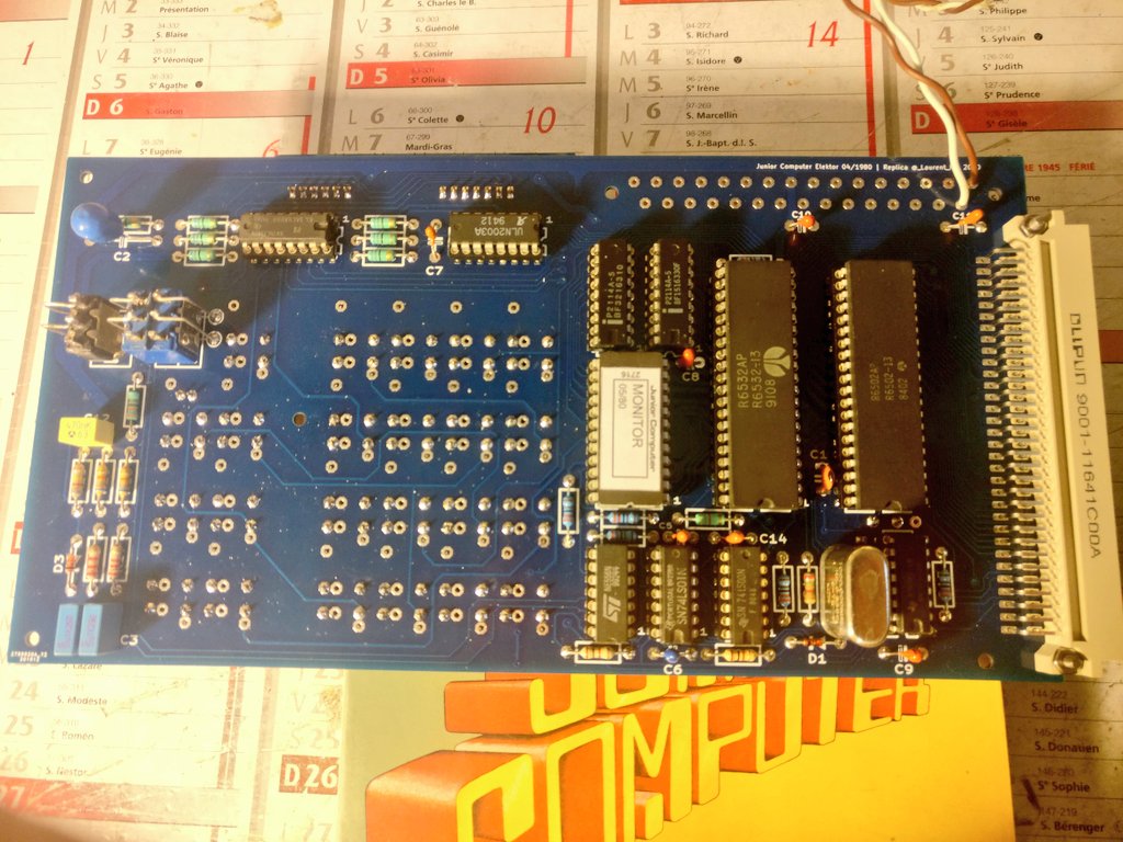
The Junior Computer is a 6502 SBC made by Elektor in 1980. It looks a lot like a KIM-1.
This is a replica PCB I made with KiCAD.
The best source of information for this computer is Elektor Magazine from 80's , but you can find a lot on this website : http://retro.hansotten.nl/6502-sbc/elektuur-junior/
This board is not a 100% accurate replica, because I have added directly on the PCB a few updates published later by Elektor :
I also replaced the 2708 EPROM by a 2716, which avoid the need of an hard to find EPROM & EPROM programmer, and has the big benefit of reducing the required power supplies from 3 (+5,-5,+12) to only +5V.
This work is licenced under CC BY-NC-SA (Attribution-NonCommercial-ShareAlike)
| Qty | Reference | Value | Comment |
|---|---|---|---|
| 1 | C1 | 10p | |
| 1 | C2 | 47µ 6V tantale | |
| 2 | C3, C4 | 100n MKH | |
| 8 | C5...C9, C10, C11, C14 | 1µ 16V tantale | |
| 1 | C12 | 470nF MKH | |
| 2 | D1, D3 | 1N4148 | |
| 1 | IC1 | MC6502 | |
| 1 | IC10 | 74LS01 | |
| 1 | IC11 | ULN2003 | |
| 1 | IC2 | 2716 | |
| 1 | IC3 | MC6532 | probably the first part to look at ! |
| 2 | IC4 IC5 | 2114 | static RAM, search on Ebay |
| 2 | IC7 IC6 | 74LS145 | |
| 1 | IC8 | NE556 | |
| 1 | IC9 | 74LS00 | |
| 1 | J2 | DIN41612 32 A+C angled male | |
| 1 | J3 | DIN41617-31 straight female | |
| 2 | R17 R19 | 2k2 | |
| 2 | R18 R20 | 68k | |
| 1 | R1 | 330K | |
| 6 | R2 R3 R4 R16 R14 R15 | 3k3 | |
| 2 | R22 R21 | 1k | |
| 1 | R23 | 820k | |
| 1 | R5 | 4k7 | |
| 1 | R6 | 330 | |
| 7 | R7 R8 R9 R10 R12 R13 R11 | 68 | |
| 21 | S1…S23 | Digitast 12.7mm | 16 black, 4 red, 1 red with integrated LED, 2 blue, but see below |
| 1 | S24 | DPDT lever switch | with soldering lugs |
| 1 | S25 | SPDT lever switch | with soldering lugs |
| 1 | X.Tal1 | 1Mhz | can be hard to find ! |
| 3 | Socket DIP-14 | ||
| 3 | Socket DIP-16 | ||
| 2 | Socket DIP-18 | ||
| 1 | Socket DIP-24 | ||
| 2 | Socket DIP-40 | ||
| 6 | Di1 ... Di6 | MAN4640A | 7 segment display |
IF you cannot find 2114 RAMs , you can try the small board on "board adapter" folder (warning : not tested !) which should allow to use a 6116 RAM instead and plugs into the 2114 sockets
The Digitast keys (https://www.digikey.com/catalog/en/partgroup/digitast-series/15959) are the most expensives parts of this project. You can also use square tactile switchs instead (but it's not as pretty !)
An other thing to consider is the marking : the black keys need white marking, which can be hard to do. So think of how you will do the marking before choosing the colors of the keys !
Use you favorite online PCB seller, and order 2 double-sided PCBs (display + computer) from the KiCad output files.
The real ones from Elektor where blue on component side and red on solder side, but if you order a blue PCB it will be close enough (and very nice).
The building is pretty straightforward (look at the original documentation). Components are soldered on one side, buttons and disply on the other side.
S24 and S25 switchs needs wires from the switchs lugs to the PCB (I used cutoff of resistor leads)
To connect the display to the main board, I used long SIL connectors (15-20mm long) soldered on both side, then I bent the display to ~30°
Don't forget the two small wire jumpers on front side : one from ground to letter "D" and the other one from K6 to the center pin.
If you want to use the file sticker-juniorcomputer.svg, first install the font "Microgramma D Extended Bold" on your system.
I use a TL866 II plus for this, but anything that works is OK.
Program the 2716 with the file 2716_junior_monitor_ram_05_1980.bin
The power supply is available on both connectors, you just need 0v and +5V (1amp should be more than enough).
All the display should light up (check that the DISPLAY switch is ON). If you see some display ON, some display OFF, it could be a bad MC6532 (don't ask how I know that ...)
If nothing happens, press the reset switch to start the computer.
Typing numbers on keyboard should update the display.
You can find test programs on http://retro.hansotten.nl
It would be great to be able to load and save data, and also to have a serial terminal for typing programs. It's exactly the purpose of the Junior Interface board ! Look into the folder "junior-interface" for more infos !
Now I'm sure you want to run BASIC on the Junior, no problem, just build the memory expansion from "junior-universal-memory" folder and you're good to go !
Any question ? --> Mastodon @LaurentFr@piaille.fr| Qty | Value | Footprint | References |
|---|---|---|---|
| 9 | 10k | elektor:Res-5 | R6, R10, R11, R14, R15, R24, R26, R27, R28 |
| 8 | 1K | elektor:Res-5 | R1, R2, R3, R4, R32, R33, R34, R35 |
| 7 | 1uF 16V | elektor:CAP-POL-3 | C10, C14, C16, C18, C19, C20, C22 |
| 6 | elektor:CONN-1 | J5, J21, J22, J23, J27, J40 | |
| 4 | elektor:PIN | J17, J18, J19, J20 | |
| 4 | 10uF 16V | elektor:CAP-POL-3 | C2, C11, C12, C13 |
| 4 | 4k7 | elektor:Res-5 | R9, R18, R22, R23 |
| 4 | Conn_01x03_Socket | elektor:Support-Jack-3.5 | J1, J2, J3, J4 |
| 3 | 1N4148 | elektor:Diod-4 | D1, D2, D3 |
| 3 | 2k2 | elektor:Res-5 | R13, R25, R31 |
| 3 | 6n8 | elektor:CAP-3 | C5, C6, C7 |
| 3 | 8k2 | elektor:Res-5 | R7, R8, R36 |
| 2 | 1uF 16V | elektor:CAP-POL-2 | C15, C21 |
| 2 | 2114 | elektor:DIL-18 | IC2, IC3 |
| 2 | 2716 | elektor:DIL-24 | IC4, IC5 |
| 2 | 74LS241 | elektor:DIL-20 | IC9, IC10 |
| 2 | 74LS243 | elektor:DIL-14 | IC11, IC12 |
| 2 | BC516 | elektor:TO-92 | T2, T3 |
| 2 | Conn_01x03_Male | elektor:CONN-3 | J12, J30 |
| 2 | LM311 | elektor:DIL-8 | IC7, IC8 |
| 2 | relay_reed | elektor:DIL-14 | Re1, Re2 |
| 1 | Q | elektor:CONN-1 | J25 |
| 1 | +12V | elektor:CONN-1 | J13 |
| 1 | +5V | elektor:CONN-1 | J8 |
| 1 | -12V | elektor:CONN-1 | J15 |
| 1 | -5V | elektor:CONN-1 | J14 |
| 1 | 0 | elektor:CONN-1 | J16 |
| 1 | 100 | elektor:Res-5 | R16 |
| 1 | 100n | elektor:CAP-3 | C8 |
| 1 | 15k | elektor:Res-5 | R21 |
| 1 | 1k | elektor:POT | P2 |
| 1 | 1k2 | elektor:Res-5 | R20 |
| 1 | 1n | elektor:CAP-3 | C4 |
| 1 | 1uF 16V | elektor:CAP-POL-2.5 | C17 |
| 1 | 220n | elektor:CAP-3 | C1 |
| 1 | 22k | elektor:Res-5 | R5 |
| 1 | 22n | elektor:CAP-3 | C3 |
| 1 | 33 | elektor:Res-5 | R37 |
| 1 | 330 | elektor:Res-5 | R17 |
| 1 | 33k | elektor:Res-5 | R29 |
| 1 | 470 | elektor:Res-5 | R19 |
| 1 | 47n | elektor:CAP-3 | C9 |
| 1 | 4M7 | elektor:Res-5 | R30 |
| 1 | 5k | elektor:POT-MULTITOUR | P1 |
| 1 | 6522 | elektor:DIL-40 | IC1 |
| 1 | 6k8 | elektor:Res-5 | R12 |
| 1 | 74LS00 | elektor:DIL-14 | IC16 |
| 1 | 74LS01 | elektor:DIL-14 | IC14 |
| 1 | 74LS27 | elektor:DIL-14 | IC13 |
| 1 | 74LS30 | elektor:DIL-14 | IC15 |
| 1 | BC547 | elektor:TO-92 | T1 |
| 1 | C64AB | elektor:DIN-41612-AB | J7 |
| 1 | C64AC | elektor:DIN-41612-AC | J6 |
| 1 | Conn_01x06_Male | elektor:CONN-6 | J29 |
| 1 | Conn_01x20_Male | elektor:Conn-20-L | J11 |
| 1 | D4 | elektor:CONN-1 | J26 |
| 1 | D5 | elektor:CONN-1 | J28 |
| 1 | DB25_Female | elektor:DB25-F-CI | J10 |
| 1 | GAL16V8 | elektor:DIL-20 | IC17 |
| 1 | NE565 | elektor:DIL-14 | IC6 |
| 1 | P | elektor:CONN-1 | J24 |
The 116 most common of 120 parts.
It measures 217.2 × 113 mm and has 2 copper layers, 1.6 mm thick.
120 parts, built around the 74LS241P-E, LM311, 74LS00SC and 74LS27P-E. The full list of its parts is on this page, with links to each part's symbol and footprint where PCBKit's library has them.
From the laurent-fr/junior_computer_replica repository on GitHub, at the commit this page was made from: the board is junior-interface/junior-interface/junior-interface.kicad_pcb and its schematic junior-bus/junior-bus.kicad_sch. PCBKit opens the board in the browser, with nothing to install.
Its repository states no licence, so its author keeps all rights: ask laurent-fr before reusing the design.
laurent-fr/junior_computer_replica
A replica of the Junior Computer (a KIM-1 clone) published by Elektor in the 80's

laurent-fr/junior_computer_replica
A replica of the Junior Computer (a KIM-1 clone) published by Elektor in the 80's

laurent-fr/junior_computer_replica
A replica of the Junior Computer (a KIM-1 clone) published by Elektor in the 80's

laurent-fr/junior_computer_replica
A replica of the Junior Computer (a KIM-1 clone) published by Elektor in the 80's

laurent-fr/junior_computer_replica
A replica of the Junior Computer (a KIM-1 clone) published by Elektor in the 80's

laurent-fr/junior_computer_replica
A replica of the Junior Computer (a KIM-1 clone) published by Elektor in the 80's

laurent-fr/junior_computer_replica
A replica of the Junior Computer (a KIM-1 clone) published by Elektor in the 80's

lynchaj/duodyne
Duodyne is a hobbyist retrocomputer system designed to run ROMWBW. It is comprised of modules on a system bus

CyberspiceHardware/BBCMicro128KRomRam
A 128K RAM sideways ROM/RAM board for the BBC Micro model B


