2 layers60 × 60 mm
Arcboard stm32-mk2
christrotter/arcboard-stm32-mk2
Next iteration of the stm32f405 board; paradigm shift means new repo.
94 partsMIT

 kyrg4z/custom-meshtastic-node1
Custom mesh node with an OLED and GNSS module.
Custom meshtastic node is an open-source printed circuit board by kyrg4z, from the kyrg4z/custom-meshtastic-node repository on GitHub, published under the CC-BY-SA-4.0 licence. It is a 2-layer board of 100 × 50 mm with 52 parts on 55 nets, routed with 545 tracks and 43 vias.
It is built around the SAM-M10Q-00B, TPS63001DRC and BQ24074RGTR, with the DW01A, USBLC6-2SC6 and 1206L150SLYR among its other parts. Its parts include 18 resistors, 17 capacitors, 6 ICs, 3 connectors and 2 switches. It belongs with the radio and wireless boards of this library.


Long-range messaging when there's no signal.
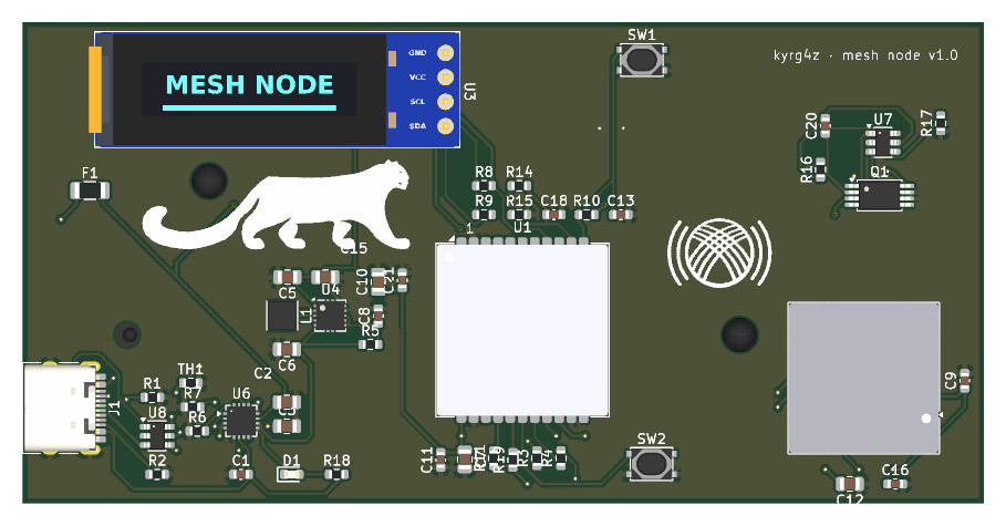
A custom Meshtastic compatible LoRa communication device that is designed for off-grid messaging in areas where cellular/internet aren't available such as hiking trails, mountains, and forests. This device provides interface for phones to be able to send messages through long range radio through a decentralized mesh network.
[!NOTE] Read about progress status in JOURNAL.md
A handheld LoRa mesh node built around the Heltec HT-CT62 module (ESP32-C3 + Semtech SX1262), with GPS, a small OLED status display, and a single 18650 cell with USB-C charging and full battery protection. The phone connects over Bluetooth and the node relays messages over 915 MHz LoRa to other nodes in the mesh.
On a chill summer day, while biking in the forest, I tried messaging my friend, but the message didn't go through simply because the cellular signal was too weak there. That day I decided to build something of my own, so meeting and sharing location in remote locations would be easier. While researching, I learned about LoRa and Meshtastic as well as Ham Radio. I thought Meshtastic would be better for my purposes, so I went with it. Since I wanted to learn PCB design and build something cool, instead of buying a Heltec, Lylygo or SenseCap, I chose to create it myself. I wanted to know how it works and how to mess with it. This project is the result and being hoenst it was quite fun. Along the way, I learned how LoRa works(DefCon talks were amazing), how to do PCB design, about ESD protection, and the GNSS system. Probably the hardest part was reading the datasheets and fixing the schematic.
No enclosure is part of this submission. The board is meant to be tested bare first, and a case may come in a later revision.
Full board assembly with every component: PRODUCTION/PCB.step
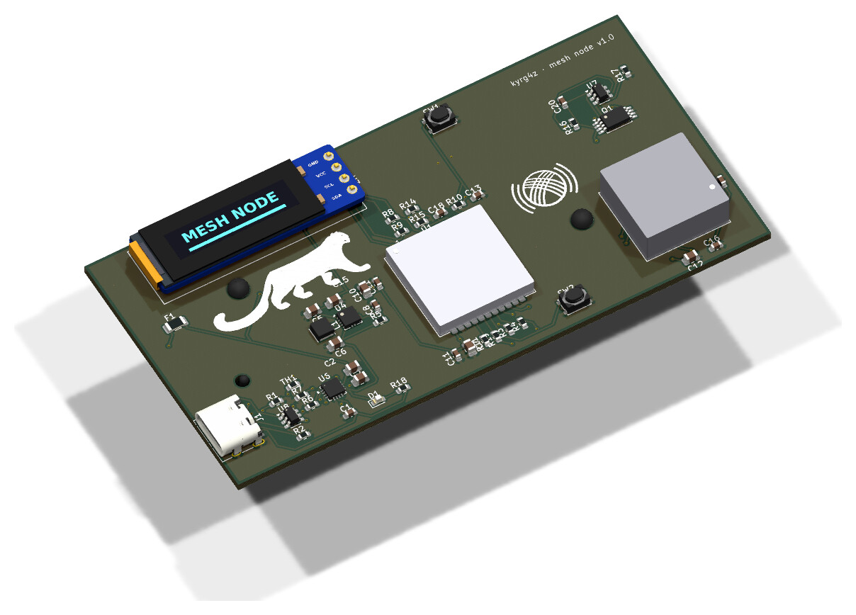
| Top | Bottom |
|---|---|
| 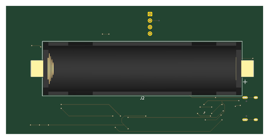 |
[!NOTE] U1 (HT-CT62), U2 (SAM-M10Q) and the OLED module (U3) are dimensioned models generated with CadQuery, since no vendor STEP was available.
Interactive KiCad viewer powered by KiCanvas:
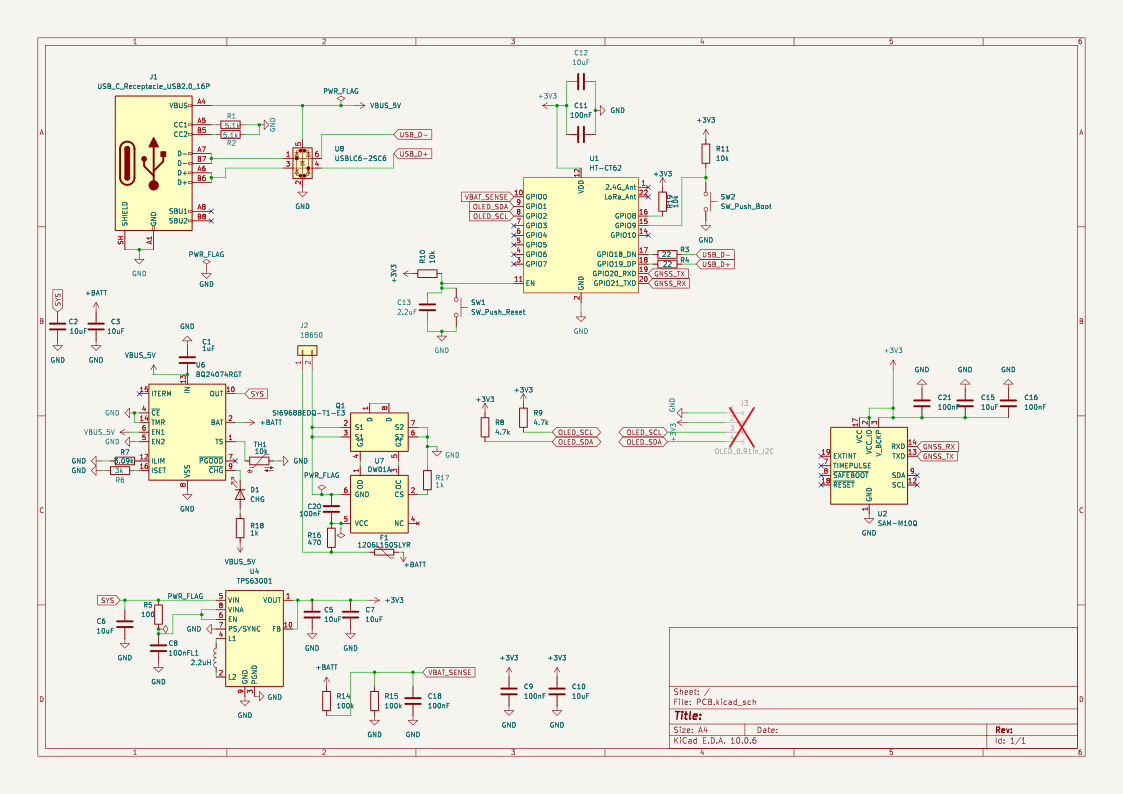
| Front | Back |
|---|---|
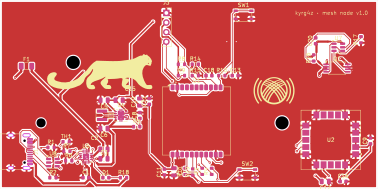 | 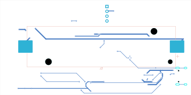 |
| # | Reference | Qty | Manufacturer | Manufacturer Part # | Value | Footprint |
|---|---|---|---|---|---|---|
| 1 | C1 | 1 | Murata Electronics | GRT188R61H105KE13D | 1uF | Capacitor_SMD:C_0603_1608Metric |
| 2 | C2,C3,C5,C6,C7,C10,C12,C15 | 8 | Cal-Chip Electronics, Inc. | GMC21X7R106K25NT | 10uF | Capacitor_SMD:C_0805_2012Metric |
| 3 | C8,C9,C11,C16,C18,C20,C21 | 7 | Murata Electronics | GCJ188R71E104KA12D | 100nF | Capacitor_SMD:C_0603_1608Metric |
| 4 | C13 | 1 | YAGEO | CC0603KRX5R8BB225 | 2.2uF | Capacitor_SMD:C_0603_1608Metric |
| 5 | D1 | 1 | Lite-On Inc. | LTST-C191KRKT | CHG | LED_SMD:LED_0603_1608Metric |
| 6 | F1 | 1 | Littelfuse Inc. | 1206L150SLYR | 1.5A PTC | Fuse:Fuse_1206_3216Metric |
| 7 | J1 | 1 | Korean Hroparts Elec | TYPE-C-31-M-12 | USB-C | Connector_USB:USB_C_Receptacle_HRO_TYPE-C-31-M-12 |
| 8 | J2 | 1 | Keystone Electronics | 1042 | 18650 | Battery:BatteryHolder_Keystone_1042_1x18650 |
| 9 | L1 | 1 | Bourns Inc. | SRN3015-2R2M | 2.2uH | Inductor_SMD:L_Taiyo-Yuden_NR-30xx |
| 10 | Q1 | 1 | Vishay Siliconix | SI6968BEDQ-T1-GE3 | SI6968BEDQ | Package_SO:TSSOP-8_4.4x3mm_P0.65mm |
| 11 | R1,R2 | 2 | Bourns Inc. | CR0603-FX-5101ELF | 5.1k | Resistor_SMD:R_0603_1608Metric |
| 12 | R3,R4 | 2 | YAGEO | RC0603FR-0722RL | 22 | Resistor_SMD:R_0603_1608Metric |
| 13 | R5 | 1 | YAGEO | RC0603FR-07100RL | 100 | Resistor_SMD:R_0603_1608Metric |
| 14 | R6 | 1 | YAGEO | RC0603FR-073KL | 3k | Resistor_SMD:R_0603_1608Metric |
| 15 | R7 | 1 | YAGEO | RC0603FR-073K09L | 3.09k | Resistor_SMD:R_0603_1608Metric |
| 16 | R8,R9 | 2 | YAGEO | RC0603FR-074K7L | 4.7k | Resistor_SMD:R_0603_1608Metric |
| 17 | R10,R11,R19,TH1 | 4 | YAGEO | AR0603FR-0710KL | 10k | Resistor_SMD:R_0603_1608Metric |
| 18 | R14,R15 | 2 | YAGEO | RC0603FR-07100KL | 100k | Resistor_SMD:R_0603_1608Metric |
| 19 | R16 | 1 | YAGEO | RC0603FR-07470RL | 470 | Resistor_SMD:R_0603_1608Metric |
| 20 | R17,R18 | 2 | YAGEO | RC0603FR-071KL | 1k | Resistor_SMD:R_0603_1608Metric |
| 21 | SW1,SW2 | 2 | C&K | PTS810SJS250SMTR LFS | Reset / Boot | Button_Switch_SMD:SW_SPST_PTS810 |
| 22 | U1 | 1 | Heltec Automation | HT-CT62 (902–928 MHz) | HT-CT62 | RF_Module:Heltec_HT-CT62 |
| 23 | U2 | 1 | u-blox | SAM-M10Q-00B | SAM-M10Q | RF_GPS:ublox_SAM-M8Q |
| 24 | U4 | 1 | Texas Instruments | TPS63001DRCR | TPS63001 | Package_SON:Texas_DRC0010J_ThermalVias |
| 25 | U6 | 1 | Texas Instruments | BQ24074RGTR | BQ24074 | Package_DFN_QFN:VQFN-16-1EP_3x3mm_P0.5mm_EP1.6x1.6mm |
| 26 | U7 | 1 | Shenzhen Slkormicro | DW01A | DW01A | Package_TO_SOT_SMD:SOT-23-6 |
| 27 | U8 | 1 | STMicroelectronics | USBLC6-2SC6 | USBLC6-2SC6 | Package_TO_SOT_SMD:SOT-23-6 |
| Part / Item | Category | Qty | Price (1 item) | Line total | Provider | Link |
|---|---|---|---|---|---|---|
| Custom PCB (fab + assembly, 2 assembled of 5) | PCB | 2 | - | $79.34 USD + parts quote | PCBWay | - |
| ER-OLEDM0.91-1B-I2C 0.91" OLED | Display | 3 | $2.80 USD | $8.40 USD | BuyDisplay | Link |
| Pulse W9015M U.FL → SMA bulkhead pigtail | LoRa antenna cable | 2 | $7.53 CAD | $15.06 CAD | Digi-Key | Link |
| Abracon AEACAC054010-S915 915 MHz whip | LoRa antenna | 2 | $10.40 CAD | $20.80 CAD | Digi-Key | Link |
| Ezurio 001-0014 2.4 GHz FlexPIFA (U.FL) | BLE antenna | 2 | $7.38 CAD | $14.76 CAD | Digi-Key | Link |
| 18650 Li-ion cell | Battery | 2 | - | already owned | - | - |
| — |
The board is fabricated and assembled by PCBWay. U3 (OLED) is marked DNP and is soldered by hand.
[!WARNING] Don't power the node with the LoRa antenna disconnected. Transmitting without a load can damage the SX1262.
Copyright © 2026 kyrg4z
| Directory | License |
|---|---|
PCB/ | CERN Open Hardware Licence Version 2 - Strongly Reciprocal — see LICENSE-HARDWARE |
images/, JOURNAL.md | Creative Commons Attribution-ShareAlike 4.0 International — see LICENSE-CONTENT |
| Qty | Value | Footprint | References |
|---|---|---|---|
| 8 | 10uF | Capacitor_SMD:C_0805_2012Metric | C2, C3, C5, C6, C7, C10, C12, C15 |
| 7 | 100nF | Capacitor_SMD:C_0603_1608Metric | C8, C9, C11, C16, C18, C20, C21 |
| 4 | 10k | Resistor_SMD:R_0603_1608Metric | R10, R11, R19, TH1 |
| 2 | 100k | Resistor_SMD:R_0603_1608Metric | R14, R15 |
| 2 | 1k | Resistor_SMD:R_0603_1608Metric | R17, R18 |
| 2 | 22 | Resistor_SMD:R_0603_1608Metric | R3, R4 |
| 2 | 4.7k | Resistor_SMD:R_0603_1608Metric | R8, R9 |
| 2 | 5.1k | Resistor_SMD:R_0603_1608Metric | R1, R2 |
| 1 | 100 | Resistor_SMD:R_0603_1608Metric | R5 |
| 1 | 1206L150SLYR | Fuse:Fuse_1206_3216Metric | F1 |
| 1 | 18650 | Battery:BatteryHolder_Keystone_1042_1x18650 | J2 |
| 1 | 1uF | Capacitor_SMD:C_0603_1608Metric | C1 |
| 1 | 2.2uF | Capacitor_SMD:C_0603_1608Metric | C13 |
| 1 | 2.2uH | Inductor_SMD:L_Taiyo-Yuden_NR-30xx | L1 |
| 1 | 3.09k | Resistor_SMD:R_0603_1608Metric | R7 |
| 1 | 3k | Resistor_SMD:R_0603_1608Metric | R6 |
| 1 | 470 | Resistor_SMD:R_0603_1608Metric | R16 |
| 1 | BQ24074RGT | Package_DFN_QFN:VQFN-16-1EP_3x3mm_P0.5mm_EP1.6x1.6mm | U6 |
| 1 | CHG | LED_SMD:LED_0603_1608Metric | D1 |
| 1 | DW01A | Package_TO_SOT_SMD:SOT-23-6 | U7 |
| 1 | HT-CT62 | RF_Module:Heltec_HT-CT62 | U1 |
| 1 | LOGO | KiCadLibraries:ilbirs_logo | G*** |
| 1 | LOGO | KiCadLibraries:tunduk_logo | G*** |
| 1 | OLED_0.91in_I2C | Connector_PinSocket_2.54mm:PinSocket_1x04_P2.54mm_Vertical | J3 |
| 1 | SAM-M10Q | RF_GPS:ublox_SAM-M8Q | U2 |
| 1 | SI6968BEDQ | Package_SO:TSSOP-8_4.4x3mm_P0.65mm | Q1 |
| 1 | SW_Push_Boot | Button_Switch_SMD:SW_SPST_PTS810 | SW2 |
| 1 | SW_Push_Reset | Button_Switch_SMD:SW_SPST_PTS810 | SW1 |
| 1 | TPS63001 | Package_SON:Texas_DRC0010J_ThermalVias | U4 |
| 1 | USBLC6-2SC6 | Package_TO_SOT_SMD:SOT-23-6 | U8 |
| 1 | USB_C_Receptacle_USB2.0_16P | Connector_USB:USB_C_Receptacle_HRO_TYPE-C-31-M-12 | J1 |
It measures 100 × 50 mm and has 2 copper layers, 1.6 mm thick.
52 parts, built around the SAM-M10Q-00B, TPS63001DRC, BQ24074RGTR and DW01A. The full list of its parts is on this page, with links to each part's symbol and footprint where PCBKit's library has them.
From the kyrg4z/custom-meshtastic-node repository on GitHub, at the commit this page was made from: the board is PCB/PCB.kicad_pcb and its schematic PCB/PCB.kicad_sch. PCBKit opens the board in the browser, with nothing to install.
Its repository publishes it under the CC-BY-SA-4.0 licence: you may reuse it on that licence's terms (keep the author's notice, and for a copyleft licence share your changes alike).
christrotter/arcboard-stm32-mk2
Next iteration of the stm32f405 board; paradigm shift means new repo.


bobberdolle1/SkySweep32
Open-source passive multi-band RF monitoring system | 855–925 MHz, 2.4 GHz, 5.8 GHz | Rev C first prototype

Outdatedcandy92/ESP32-Eink
A tiny E-Ink display driver board featuring an ESP32-C3 and an onboard battery charging IC. It wirelessly drives a 2.13-inch E-Ink display and is designed for portable, ultra-low-power projects such as status displays…

ThVerstappen/AI-Fx580VNX
Revision mới nhất hoàn tất ngày 11/10/2026. Mở FX580MainEPDLAYOUTV8.kicadpro bằng KiCad 10.0.5; PCB và schematic cùng tên. Thư viện local dùng ${KIPRJMOD}/lib.

Projeto-Guarda-Rios/PCB
O repositório para a PCB do Projeto Guarda Rios! Inclui todos os ficheiros relacionados com a PCB!