Skip to the content
PCBKitNew board
4 layers111.8 × 69.8 mmDriver board, the printed circuit board in 3D

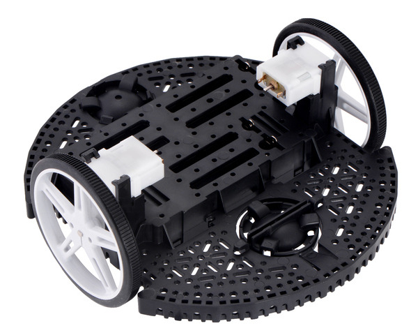
A small SLAM capable robot built on the Pololu Romi chassis

Size
111.8 × 69.8 mm
Copper layers
4
Thickness
1.59 mm
Parts
70
Nets
67
Pads
254
Tracks, vias
344, 236
Pours
42
Routed
Yes
KiCad
KiCad 10.0 (file 20260206)
Created
14 Jun 2020
Updated
4 Aug 2026

Overview

Driver board is an open-source printed circuit board by kylestew, from the kylestew/roamer-bot repository on GitHub. It is a 4-layer board of 111.8 × 69.8 mm with 70 parts on 67 nets, routed with 344 tracks and 236 vias.

It is built around the STM32F103CBT6, DRV8838DSG and USBLC6-2SC6, with the AO3401A, AO4407A and SK-3296S-01-L2 among its other parts. Its parts include 23 capacitors, 18 resistors, 5 ICs, 4 connectors and 2 diodes. It belongs with the robots and motor control boards and the STM32 boards of this library.

Main components

6

README

README.md

roamer-bot

A small robotics learning platform built on the Pololu Romi chassis.

The current direction is a custom-core Studio Mission Rover: Romi chassis, custom MCU + motor-control PCB, laptop tether first, telemetry from day one, and no ROS in the core system until the low-level robot is understood.

romi chassis

Current Direction

The project is moving from the original Romi 32U4 + Raspberry Pi + ROS approach toward a custom-core learning build:

  • Treat the old implementation as historical/reference material.
  • Use the Romi chassis as the mechanical target.
  • Build a custom MCU + motor-control PCB that replaces the purchasable Pololu Romi control board.
  • Keep the first version tethered to a laptop.
  • Capture telemetry from day one.
  • Keep ROS out of the core system until the custom board, telemetry, and motor-control loop are understood.

Current Structure

  • hardware/: active Rev A PCB and mechanical-constraint work.
  • firmware/: active custom MCU firmware work.
  • host/: active laptop tether, telemetry capture, and test tooling work.
  • legacy/old-romi/: previous Romi 32U4 + Raspberry Pi + ROS implementation, kept only as reference.
  • docs/: datasheets, Romi reference assets, and legacy dependency references.

Planning

First Milestone

Teleop + encoder logging + safe stop:

  • Command left and right motors from a laptop or simple host.
  • Read left and right encoder counts.
  • Stream basic telemetry.
  • Stop motors on command timeout.
  • Save a short bench or floor test log on the host.

Parts

70
QtyValueFootprintReferences
12100nCapacitor_SMD:C_0402_1005MetricC3, C4, C5, C6, C7, C9, C11, C12, C14, C15, C18, C19
510kResistor_SMD:R_0402_1005MetricR1, R10, R11, R14, R15
4100kResistor_SMD:R_0402_1005MetricR12, R13, R16, R18
410uCapacitor_SMD:C_0805_2012MetricC8, C10, C13, C17
4MountingHoleCustomParts:MountingHole_2.3mm_2-56H1, H2, H3, H4
31kResistor_SMD:R_0603_1608MetricR20, R21, R23
210pCapacitor_SMD:C_0402_1005MetricC1, C2
222uCapacitor_SMD:C_1206_3216MetricC20, C21
25k1Resistor_SMD:R_0402_1005MetricR6, R7
2DRV8838Package_SON:WSON-8-1EP_2x2mm_P0.5mm_EP0.9x1.6mmU3, U4
1100kResistor_SMD:R_0603_1608MetricR22
110nCapacitor_SMD:C_0402_1005MetricC22
116MhzCrystal:Crystal_SMD_3225-4Pin_3.2x2.5mmY1
11k5Resistor_SMD:R_0402_1005MetricR5
11uCapacitor_SMD:C_0603_1608MetricC23
122.1kResistor_SMD:R_0402_1005MetricR19
1220uCapacitor_SMD:CP_Elec_6.3x7.7C16
133kResistor_SMD:R_0402_1005MetricR17
15.6uInductor_SMD:L_APV_ANR8065L1
1AO3401APackage_TO_SOT_SMD:SOT-23Q1
1AO4407ACustomParts:AO4407A_SO-8_GSDQ2
1BATT (2xAA)CustomParts:Romi_Chassis_BatteryContactPair_2Slot_14_50mmBT2
1BATT (4xAA)CustomParts:Romi_Chassis_BatteryContactPair_2Slot_14_50mmBT1
1CAPYBARA_ARTWORKCapybara_SunglassesG1
1CONN_MOTOR_LConnector_PinSocket_2.54mm:PinSocket_1x06_P2.54mm_VerticalJ4
1CONN_MOTOR_RConnector_PinSocket_2.54mm:PinSocket_1x06_P2.54mm_VerticalJ3
1Conn_ARM_JTAG_SWD_10Connector_PinHeader_1.27mm:PinHeader_2x05_P1.27mm_Vertical_SMDJ1
1LMR51430XDDCRPackage_TO_SOT_SMD:SOT-23-6U5
1PTC_2.6A_16VFuse:Fuse_1812_4532MetricF1
1PWR_ON_LEDLED_SMD:LED_0603_1608MetricD1
1SK-3296S-01-L2CustomParts:SW_SPDT_RightAngle_XKB_SK-3296S-01-L2SW2
1STATUSLED_SMD:LED_0805_2012MetricD2
1STM32F103CBT6Package_QFP:LQFP-48_7x7mm_P0.5mmU1
1SW_PushButton_Switch_SMD:SW_SPST_TS-1088-xR020SW1
1TP_3V3TestPoint:TestPoint_Pad_2.0x2.0mmTP1
1TP_BATTestPoint:TestPoint_Pad_2.0x2.0mmTP3
1TP_BAT_SWTestPoint:TestPoint_Pad_2.0x2.0mmTP4
1TP_GNDTestPoint:TestPoint_Pad_2.0x2.0mmTP2
1USBLC6-2SC6Package_TO_SOT_SMD:SOT-23-6U2
1USB_C_Receptacle_USB2.0_16PConnector_USB:USB_C_Receptacle_G-Switch_GT-USB-7010ASVJ2

Questions

How big is the Driver board PCB?

It measures 111.8 × 69.8 mm and has 4 copper layers, 1.59 mm thick.

What parts does the Driver board use?

70 parts, built around the STM32F103CBT6, DRV8838DSG, USBLC6-2SC6 and AO3401A. The full list of its parts is on this page, with links to each part's symbol and footprint where PCBKit's library has them.

Where can I download the Driver board KiCad files?

From the kylestew/roamer-bot repository on GitHub, at the commit this page was made from: the board is hardware/driver-board/driver-board.kicad_pcb and its schematic hardware/driver-board/_restore_backup_2026-07-17T22-34-31-820/driver-board.kicad_sch. PCBKit opens the board in the browser, with nothing to install.

Can I use the Driver board design in my own project?

Its repository states no licence, so its author keeps all rights: ask kylestew before reusing the design.

Similar boards

  • 2 layers62 × 6 mmTableLight, the printed circuit board in 3D

    TableLight

    jonny190/TableLight

    A 3D-printable, battery-powered, USB-C rechargeable table lamp in the classic "Poldina" shape - honeycomb disc base, thin stem, down-firing cone shade with a white top - running WLED on an ESP32, with a capacitive touch…

    72 partsMIT
  • 4 layers140 × 100 mmDc usv, the printed circuit board in 3D

    Dc usv

    TobleMiner/DC-UPS

    A small DC UPS, designed to keep small appliances like consumer network equipment running during power outages

    351 parts223CERN-OHL-P-2.0
  • 4 layers66 × 100 mmPixy M2, the printed circuit board in 3D

    Pixy M2

    Galm007/KiCad-Pixy-M2

    Schematic For Our Micromouse Robot "Pixy M2"

    79 partsMIT
  • 4 layersRound LED Flash, the printed circuit board in 3D

    Round LED Flash

    xmyoot/custom-round-pcb-led-flash

    Custom circular ring PCB LED flash controller prototype

    237 parts
  • 4 layers120 × 75 mmRedcat51ii flat panel controller revc, the printed circuit board in 3D

    Redcat51ii flat panel controller revc

    pulikantitarun/redcat51ii-automated-flat-panel

    Automated flat panel controller, PCB, firmware, and 3D-printable hardware for the William Optics RedCat 51 II and ASIAIR Plus

    68 parts2AGPL-3.0
  • 4 layers90 × 60 mmBench psu, the printed circuit board in 3D

    Bench psu

    PaulBichl/VibePCB-bench-psu

    USB-C PD (20 V) powered bench supply, 2 independent channels, 1.6-16.6 V / 3 A each, constant voltage / constant current, designed with VibePCB.

    206 parts1
  • 4 layers60 × 90 mm2027Payload, the printed circuit board in 3D

    2027Payload

    Bmcneley/2027Payload

    KiCad project files for 2027 Cy Launch payload PCB.

    96 parts
  • 4 layers82.1 × 80.2 mmSeguidor de linhas 4camada2-2026-1, the printed circuit board in 3D

    Seguidor de linhas 4camada2-2026-1

    wvianna/mcp-kicad-vscode

    Workspace que combina um servidor MCP para automação de design de PCB com KiCad e o projeto de hardware (placa de circuito impresso) desenvolvido com ele.

    97 parts