2 layers140.5 × 30 mm
Type e
google/mozc-devices
Circuit diagrams and firmware source code for Gboard DIY keyboards
16 parts3kApache-2.0
 kylecmathias/FlipperInfinity2
Handheld multi-protocol signal analysis device — NFC, RFID, sub-GHz RF, IR, and WiFi on a custom ESP32 PCB with FreeRTOS firmware and LVGL touchscreen UI
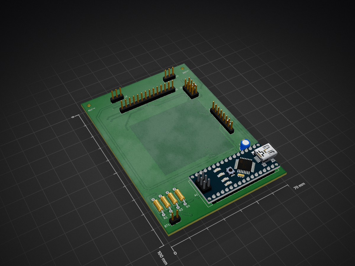
Flipper infinity pcb is an open-source printed circuit board by kylecmathias, from the kylecmathias/FlipperInfinity repository on GitHub. It is a 2-layer board of 70 × 100 mm with 16 parts on 30 nets, routed with 356 tracks and 36 vias.
Its parts include 5 connectors, 4 resistors and 3 capacitors. It belongs with the radio and wireless and home automation and IoT boards and the ESP32 and AVR (ATmega, ATtiny) boards of this library.
Ongoing — Hardware complete, PCB designed, firmware in active development
A handheld multi-protocol signal analysis device built on a custom ESP32 PCB, integrating NFC/RFID, sub-GHz RF, infrared, and WiFi into a single embedded platform with an on-device touchscreen interface.
| Module | Protocol | Function |
|---|---|---|
| PN532 | SPI | NFC/RFID read/write/emulate |
| CC1101 | SPI | Sub-GHz RF (433MHz) |
| IR Transmitter | GPIO | Infrared signal transmission |
| IR Receiver | GPIO | Infrared signal capture |
| Arduino Nano ESP32 | — | Main controller, WiFi, promiscuous packet capture |
| ILI9341 TFT Touchscreen | SPI | On-device UI (XPT2046 touch controller) |
| NiMH AA x6 | — | 7.2V battery pack, onboard voltage monitoring |
Custom 2-layer PCB designed in KiCad integrating all modules on a single board with a shared SPI bus, dedicated power rails, and RF-aware layout.
Designed from scratch in KiCad. Two-layer board with:
| Signal | ESP32 Pin | Connected To |
|---|---|---|
| SCK | D13 | TFT, PN532, CC1101 (shared SPI bus) |
| MOSI | D11 | TFT, PN532, CC1101 (shared SPI bus) |
| MISO | D12 | TFT, PN532, CC1101 (shared SPI bus) |
| TFT_SS | A2 | TFT display CS |
| T_SS | A4 | TFT touch CS |
| TFT_RST | D8 | TFT reset |
| DC | D9 | TFT data/command |
| LED | D10 | TFT backlight |
| T_IRQ | D2 | Touch interrupt |
| PN532_SS | A5 | PN532 CS |
| PN532_IRQ | D5 | PN532 interrupt |
| PN532_RST0 | D6 | PN532 reset |
| CC1101_SS | A7 | CC1101 CS |
| CC1101_GDO0 | D3 | CC1101 packet interrupt |
| IR_TX_DAT | D1 | IR transmitter |
| IR_RX_DAT | D0 | IR receiver |
| BATTERY_LVL | A3 | Battery voltage ADC (150k/100k divider) |
| BATTERY_SRC | D7 | USB/battery source detect (10k/20k divider) |
| VIN | VIN | 7.2V NiMH battery pack |
Written in C++ using ESP-IDF with FreeRTOS. Each protocol runs as an isolated task, scheduled cooperatively to avoid resource contention across shared buses.
Network scanning, packet monitoring, device inventory, deauthentication, file server, MAC spoofing, captive portal, beacon spam
BLE device scanner, packet sniffer, device logger
Read, write, emulate, sniff — supports Mifare Classic cards
Read, write, emulate
Transmit, receive, universal remote, signal replay
Frequency analyzer, listen, decode, replay, transmit
FlipperInfinity/
├── include/                # Header files to include (.hpp)
├── src/                    # Firmware source (.cpp, ESP-IDF) and build files (CMakeLists, idf_component)
│   ├── ui/                 # UI files generated with EEZ Studio (.c, .h)
├── hardware/
│   ├── schematic/          # KiCad schematic (.kicad_sch)
│   ├── pcb/                # KiCad PCB layout (.kicad_pcb)
│   └── gerbers/
│       └── v1.0/           # Manufacturing files for JLCPCB
├── partitions.csv          # ESP32s3 partitions
├── sdkconfig.defaults      # Configuration overrides
├── platformio.ini          # Platformio configuration
└── README.mdESP32 · ESP-IDF · FreeRTOS · LVGL · SquareLine Studio · C++ · SPI · PN532 · CC1101 · KiCad
| Qty | Value | Footprint | References |
|---|---|---|---|
| 2 | 100nF | Capacitor_SMD:C_0805_2012Metric | C1, C3 |
| 1 | 100kΩ | Resistor_THT:R_Axial_DIN0207_L6.3mm_D2.5mm_P10.16mm_Horizontal | R4 |
| 1 | 10kΩ | Resistor_THT:R_Axial_DIN0207_L6.3mm_D2.5mm_P10.16mm_Horizontal | R1 |
| 1 | 10uF | Capacitor_THT:CP_Radial_D5.0mm_P2.00mm | C4 |
| 1 | 150kΩ | Resistor_THT:R_Axial_DIN0207_L6.3mm_D2.5mm_P10.16mm_Horizontal | R3 |
| 1 | 20kΩ | Resistor_THT:R_Axial_DIN0207_L6.3mm_D2.5mm_P10.16mm_Horizontal | R2 |
| 1 | 7.2V | Connector_PinHeader_2.54mm:PinHeader_1x02_P2.54mm_Vertical | BT1 |
| 1 | Arduino_Nano_ESP32 | Module:Arduino_Nano | A1 |
| 1 | CC1101_RF_433MHz | Connector_PinHeader_2.54mm:PinHeader_2x04_P2.54mm_Vertical | J2 |
| 1 | ILI9341_TFT | Connector_PinHeader_2.54mm:PinHeader_1x14_P2.54mm_Vertical | J5 |
| 1 | IR_RX | Connector_PinHeader_2.54mm:PinHeader_1x03_P2.54mm_Vertical | J3 |
| 1 | IR_TX | Connector_PinHeader_2.54mm:PinHeader_1x03_P2.54mm_Vertical | J4 |
| 1 | PN532_NFC | Connector_PinHeader_2.54mm:PinHeader_1x08_P2.54mm_Vertical | J1 |
The 14 most common of 16 parts.
It measures 70 × 100 mm and has 2 copper layers, 1.6 mm thick.
16 parts. The full list of its parts is on this page, with links to each part's symbol and footprint where PCBKit's library has them.
From the kylecmathias/FlipperInfinity repository on GitHub, at the commit this page was made from: the board is hardware/pcb/flipper_infinity_pcb.kicad_pcb and its schematic hardware/schematic/flipper_infinity_pcb.kicad_sch. PCBKit opens the board in the browser, with nothing to install.
Its repository states no licence, so its author keeps all rights: ask kylecmathias before reusing the design.
google/mozc-devices
Circuit diagrams and firmware source code for Gboard DIY keyboards

conorpp/u2f-zero
U2F USB token optimized for physical security, affordability, and style

rusefi/rusefi
rusefi - GPL internal combustion engine control unit

VoronDesign/Voron-Hardware
Cool Hardware designed by the Voron Design group

hoglet67/RGBtoHDMI
Bare-metal Raspberry Pi project that provides pixel-perfect sampling of Retro Computer RGB/YUV video and conversion to HDMI

hackclub/OnBoard
💡 Join 1,000 teenagers and make your first PCB with a $100 grant!

