


2 layers150 × 70 mm
Nixie
kuvychko/universal-nixie-display
Six IN-14 Nixie tubes, an A101 dekatron and an ESP32 touchscreen in one desktop display: a clock, timer and toy, and a numeric display for a computer over USB.
99 parts1

Six IN-14 Nixie tubes, an A101 dekatron and an ESP32 touchscreen in one desktop display: a clock, timer and toy, and a numeric display for a computer over USB. Open hardware (KiCad) and firmware, with a site that explains how the tubes work.
Dekatron is an open-source printed circuit board by kuvychko, from the kuvychko/universal-nixie-display repository on GitHub. It is a 2-layer board of 100 × 85 mm with 165 parts on 83 nets, routed with 731 tracks and 370 vias.
It is built around the LM5156HPWP, LM66100DCK and TLV3011AIDBVR, with the CC1206JPX7R9BB104, MKS4G034704F00MSSD and ES1J among its other parts. Its parts include 45 resistors, 38 capacitors, 12 diodes, 7 ICs and 4 transistors. It belongs with the lEDs and displays boards and the ESP32 and RP2040 boards of this library.


A programmable desktop display: six IN-14 Nixie tubes in a row, one A101 dekatron, a 2.8" ESP32 touchscreen and a rotary encoder, in a matte PLA enclosure on a tilt base. It is meant to be an enjoyable object on its own (clock, timer, demo) and a numeric output device for a computer, Raspberry Pi or experiment, driven over USB serial with a small SCPI-style command set.
Companion site: kuvychko.github.io/universal-nixie-display · Interactive explainer: How a dekatron counts
The first tube to run is the A101, on a bench fixture: a printed housing for its socket, a shroud over the tube, and a white clamshell around a perf board with a resistor divider and two step buttons (bench test). It strikes, holds its glow and steps reliably in both directions; the video shows it stepping from a 400 V supply.
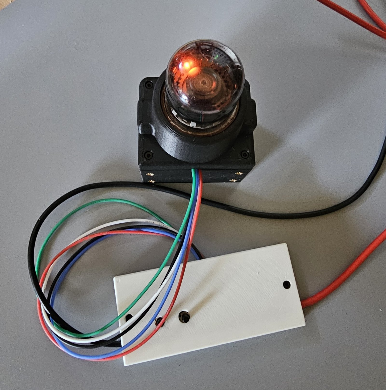
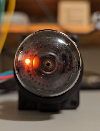
The bench fixture running from a 400 V supply (2026-10-20), and a still from the video of the tube stepping (2026-10-19).
The socket housing and shroud are not just for the bench: they go into the finished display as they are, with the dekatron held horizontally, its end facing the viewer. The M3 inserts in the housing's side faces are its mounting points in the enclosure. Print files and hardware are in enclosure/.
On 2026-10-25 the A101 ran from the first assembled controller/PSU board: the board's own HV
converter, bias supplies and guide drivers, with the RP2040 stepping the glow and counting its
passes over the index cathode. The video shows a demo loop: glow held still, slow rotation both
ways, speeding up to 200 steps/s, and a back-and-forth swing
(tools/dekatron_demo.py, on the
bring-up firmware). Stepping runs of up to 200 steps/s
in both directions counted every index pass exactly. With the tube lit the converter first held
only about 415 V of its 451 V setpoint; noise at the current-sense pin was ending its cycles
early. Since 2026-10-26, after three small reworks with kit parts, it regulates at the setpoint
with the tube lit (assembly log).
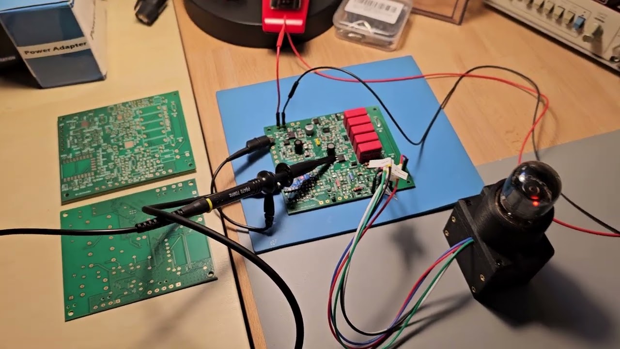
The first controller/PSU board driving the A101 (video, 2026-10-25).
Phase 1D — dekatron controller/PSU bring-up (boards from PCBWay received 2026-10-15; parts from Mouser 2026-10-16). Schematics, simulations, PCB and fab files are done; the board is now being assembled and brought up section by section. The planning baseline is docs/project_plan.md; the design decisions and open items are tracked in docs/hardware.md.
| Phase | Deliverable | State |
|---|---|---|
| 1A | Dekatron board architecture and power budget for 12 VDC input | Done |
| 1B | Hierarchical schematics and simulation evidence | Done (open simulation items in docs/hardware.md) |
| 1C | Dekatron controller/PSU PCB, BOM, fab files | Done: boards and parts received |
| 1D | Sectional bring-up and standalone firmware | In progress |
| 2 | Nixie PSU qualification and six-tube controller/mount | Not started |
| 3 | ESP32 UI, encoder, I2C master, USB host commands | Not started |
| 4 | Enclosure | Not started |
| 5 | Rev A release | Not started |
Readable without KiCad. Board as fabricated (commit f4fd414, ordered 2026-10-09); the schematic title block still reads "Rev A draft". Not yet fully validated: bring-up is in progress (Phase 1D); on board 1 the HV supply and tube drive run, the HV at its setpoint under load after reworks to the current sense and switching frequency (docs/bringup.md).
| What | File |
|---|---|
| Schematic (PDF, 4 sheets) | hardware/dekatron/docs/dekatron-schematic.pdf |
| Board renders | top, bottom |
| Bill of materials | hardware/dekatron/bom.csv |
| Assembly checklist | hardware/dekatron/assembly.md |
| Gerbers and drill files | hardware/dekatron/fab/ |
| Bring-up results | docs/bringup.md |
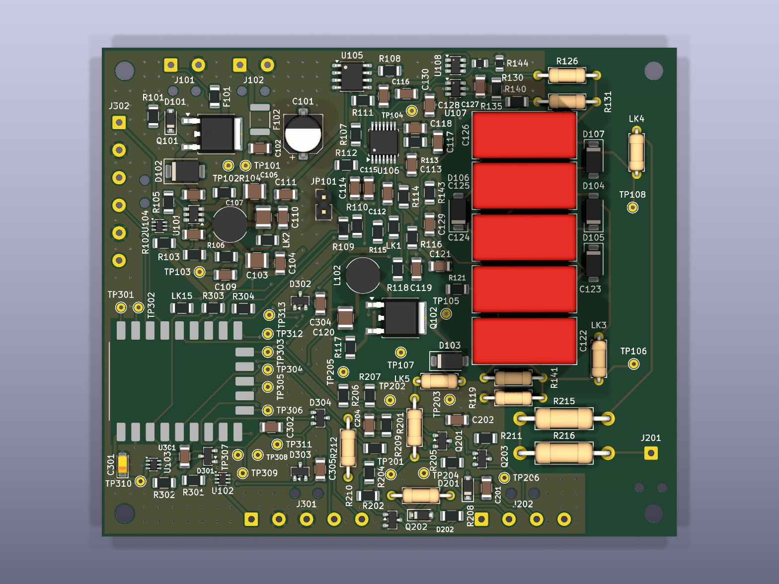
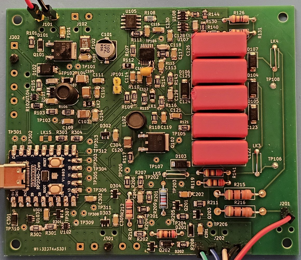
Render and board 1 as assembled by hand (2026-10-27). The yellow disc capacitor beside U106 is a bring-up rework: 470 pF at the converter's current-sense pin.
 12 VDC adapter ──┬──────────────► purchased Nixie HV module (~170-180 V) ──► Nixie controller/mount
                  │                                                           (6× IN-14, 3× HV5622, RP2040-Zero)
                  └──► dekatron controller/PSU ──► A101 (HV, bias, guide drive, index sense, RP2040-Zero)
                         │ 5 V buck out
                         ▼
                   ESP32 2.8" display board ◄── USB-C to host (SCPI-style serial)
                   (UI, encoder, presets, I2C master)
                         │ I2C, 3.3 V
                         └──► dekatron controller, Nixie controller
The ESP32 owns what is displayed; the RP2040 controllers own time-sensitive sequences and hardware state. See docs/architecture.md.
| Document | Contents |
|---|---|
| docs/project_plan.md | Planning baseline: scope, decisions, phases and acceptance gates |
| docs/architecture.md | Power distribution, board boundaries, ownership |
| docs/hardware.md | Electrical design, open decisions, harness tables |
| docs/i2c_protocol.md | Versioned controller command/status contracts |
| docs/host_interface.md | USB serial / SCPI-style host contract |
| docs/bringup.md | Module bring-up procedures and acceptance results |
| docs/development.md | Toolchains, KiCad workflow, generated-file policy |
| docs/references.md | Datasheets, source designs, attribution and reuse terms |
| docs/companion_site.md | Plan for the companion website (website/); the published site is here |
| Path | Contents |
|---|---|
hardware/dekatron/ | Dekatron controller/PSU KiCad project; simulation/ holds supply and drive/sense models |
hardware/nixie/ | Nixie controller/mount KiCad project (planned, Phase 2) |
hardware/power/ | Purchased Nixie PSU specification and system power harness (planned, Phase 2) |
hardware/lib/ | Shared symbols and footprints (planned; the dekatron board's own library is in hardware/dekatron/lib/) |
firmware/display/ | ESP32 main application, PlatformIO (planned, Phase 3) |
firmware/dekatron/ | RP2040 dekatron controller and standalone diagnostics (planned, Phase 1D) |
firmware/nixie/ | RP2040 Nixie controller (planned, Phase 2) |
firmware/common/ | Shared protocol definitions (planned) |
enclosure/ | Printed parts, one folder per assembly (SOLIDWORKS source, STEP, 3MF); index and print settings in its README |
tools/ | KiCad generators (schematic, placement, routing, silkscreen) and the site checker; serial client and bring-up scripts to come |
characterization/ | Dated measurements: supply, homing, thermal, reliability (none yet) |
tests/ | Host protocol/formatting tests, hardware test scripts (planned) |
website/ | Companion site source (MkDocs Material; mkdocs.yml at the root) |
[!WARNING] This project uses dangerous voltages. The dekatron runs from about 450 V DC and the Nixies from about 170-180 V DC. A shock at these voltages can cause serious injury or death, and capacitors can hold a charge after the power is off. If you build, test or copy anything here, you do so entirely at your own risk. Work on it only if you understand high-voltage circuits and know what you are doing. The designs and documents are provided as is, without warranty of any kind (see LICENSE).
The A101 bench test (docs/bringup.md; video) is the most exposed part of the project: open wiring on a perf board, the anode at up to 450 V and every other wire at 50-106 V, none of them at ground. If you try it:
On the boards, discharge paths, clearances and probe ratings are design requirements, not afterthoughts (project plan §4). Printed plastic parts keep fingers away; they are not high-voltage insulation.
The dekatron controller/PSU boards were made by PCBWay, who
sponsored their fabrication. Ordering was easy and smooth: upload the Gerber zip from
hardware/dekatron/fab/, pick the options and go. What stands out is
how much information their website gives, from exactly what you are ordering to where your order
is in production. There is even a full walk-through of how a board is made, step by step:
PCB manufacturing process. Beyond bare boards they
also make SMD stencils and offer assembly, CNC machining and 3D printing.
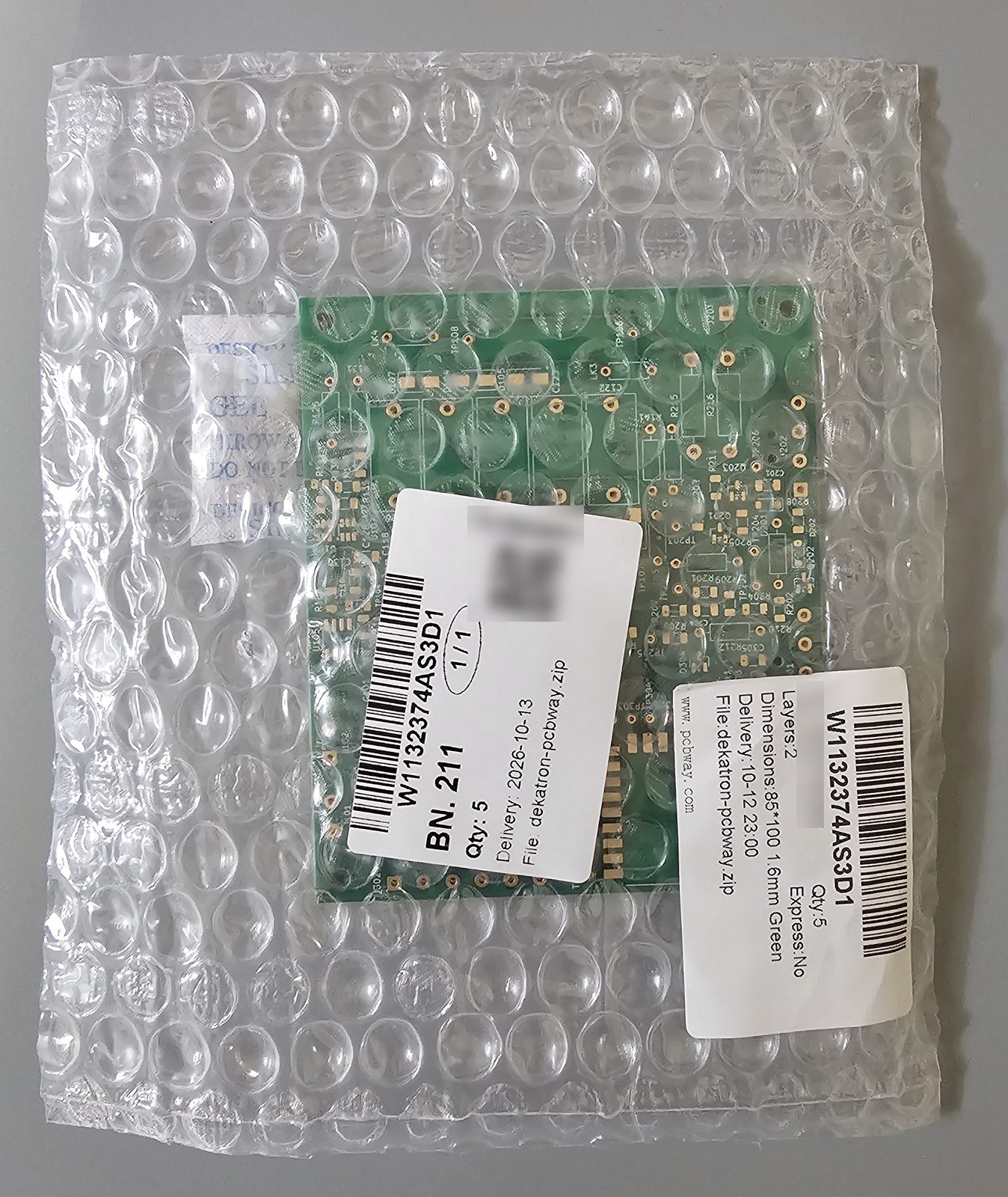
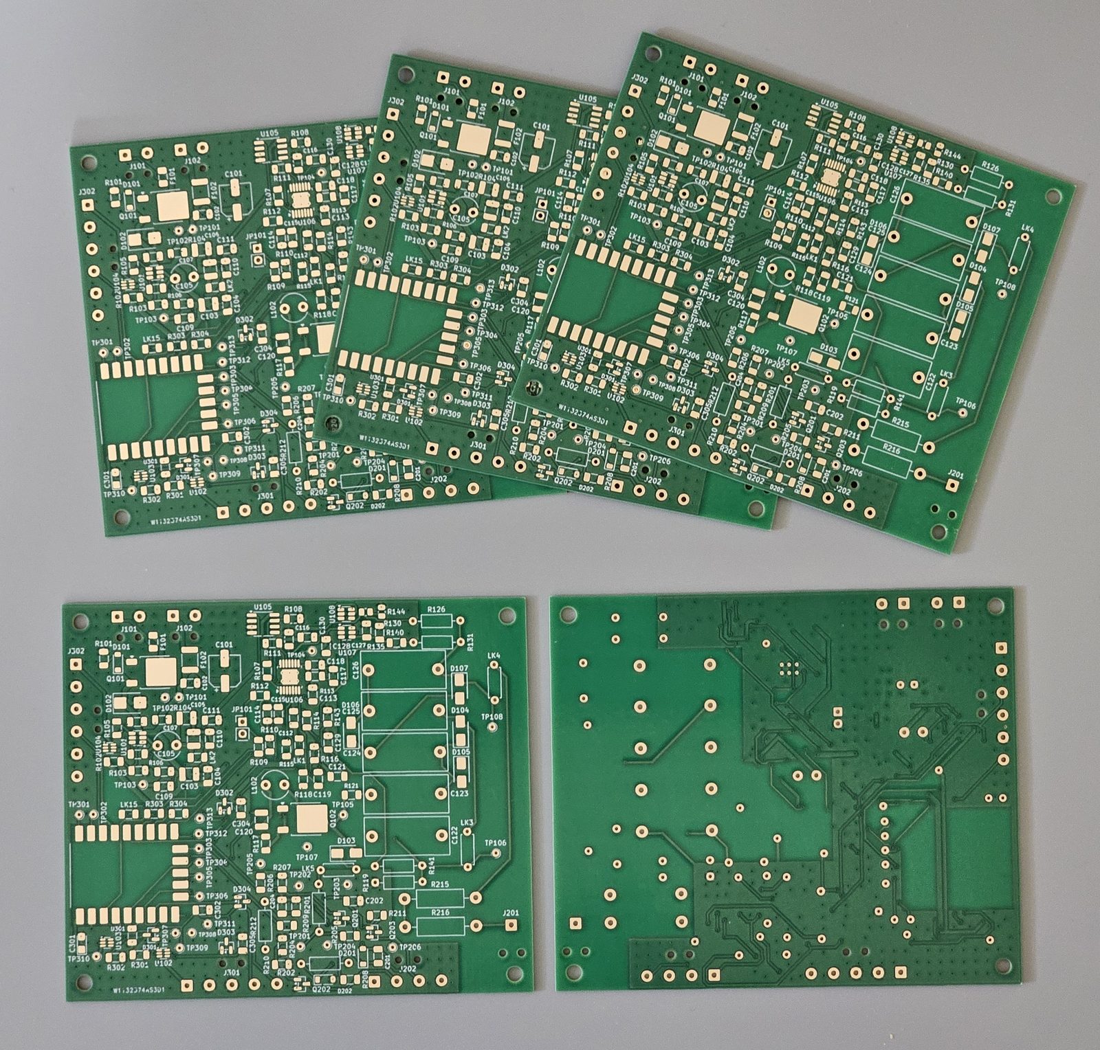
The Gerbers went up on the evening of 2026-10-08 and the five boards were on the bench on 2026-10-15. They came sealed in bubble wrap with a silica-gel desiccant pack, and the label lists the order, the uploaded file, size, layer count, thickness and quantity. The edges are milled clean: no break-away tab remnants to file, so the boards were ready to use straight out of the bag.
Thank you, PCBWay, for supporting an open-source hardware project!
Hardware, enclosure, documentation and the companion site's content: CERN-OHL-P v2. Firmware, tools, tests and the site's JavaScript: MIT. See LICENSE.
| Qty | Value | Footprint | References |
|---|---|---|---|
| 11 | 0.1uF | Capacitor_SMD:C_1206_3216Metric | C102, C104, C105, C109, C110, C111, C115, C121, C128, C130, C302 |
| 7 | 10k | Resistor_SMD:R_1206_3216Metric | R101, R109, R113, R114, R204, R206, R209 |
| 6 | cable tie | TIE_J101, TIE_J102, TIE_J201, TIE_J202, TIE_J301, TIE_J302 | |
| 5 | 0.47uF 400V | Capacitor_THT:C_Rect_L18.0mm_W8.0mm_P15.00mm_FKS3_FKP3 | C122, C123, C124, C125, C126 |
| 5 | ES1J | Diode_SMD:D_SMA | D103, D104, D105, D106, D107 |
| 4 | 0 | Resistor_SMD:R_1206_3216Metric | LK1, LK2, LK15, R112 |
| 4 | 100k | Resistor_SMD:R_1206_3216Metric | R105, R110, R116, R301 |
| 4 | BAT54S | Package_TO_SOT_SMD:SOT-23 | D301, D302, D303, D304 |
| 4 | GND | TestPoint:TestPoint_THTPad_D1.5mm_Drill0.7mm | TP102, TP107, TP206, TP311 |
| 4 | MountingHole_3.2mm_M3 | MountingHole:MountingHole_3.2mm_M3 | H1, H2, H3, H4 |
| 3 | 1nF | Capacitor_SMD:C_1206_3216Metric | C127, C129, C204 |
| 3 | LINK | Resistor_THT:R_Axial_DIN0207_L6.3mm_D2.5mm_P7.62mm_Horizontal | LK3, LK4, LK5 |
| 3 | LM66100 | Package_TO_SOT_SMD:SOT-363_SC-70-6 | U102, U103, U104 |
| 2 | 100nF | Capacitor_SMD:C_1206_3216Metric | C303, C305 |
| 2 | 10nF | Capacitor_SMD:C_1206_3216Metric | C117, C304 |
| 2 | 10uF 35V | Capacitor_SMD:C_1210_3225Metric | C103, C120 |
| 2 | 13.7k | Resistor_SMD:R_1206_3216Metric | R106, R143 |
| 2 | 2.2M | Resistor_THT:R_Axial_DIN0207_L6.3mm_D2.5mm_P10.16mm_Horizontal | R119, R141 |
| 2 | 2.7M | Resistor_THT:R_Axial_DIN0207_L6.3mm_D2.5mm_P10.16mm_Horizontal | R126, R131 |
| 2 | 22uF 25V | Capacitor_SMD:C_1210_3225Metric | C106, C107 |
| 2 | 3.0k | Resistor_SMD:R_0805_2012Metric | R130, R144 |
| 2 | 330k | Resistor_THT:R_Axial_DIN0411_L9.9mm_D3.6mm_P15.24mm_Horizontal | R215, R216 |
| 2 | 4.7k | Resistor_SMD:R_1206_3216Metric | R303, R304 |
| 2 | 470k | Resistor_SMD:R_1206_3216Metric | R205, R208 |
| 2 | 47k | Resistor_SMD:R_1206_3216Metric | R207, R210 |
| 2 | MMBTA42 | Package_TO_SOT_SMD:SOT-23 | Q201, Q202 |
| 2 | TLV3011 | Package_TO_SOT_SMD:SOT-23-6 | U107, U108 |
| 1 | +3V3 | TestPoint:TestPoint_THTPad_D1.5mm_Drill0.7mm | TP309 |
| 1 | +5V | TestPoint:TestPoint_THTPad_D1.5mm_Drill0.7mm | TP103 |
| 1 | 0.1uF 100V | Capacitor_SMD:C_1206_3216Metric | C201 |
| 1 | 0.22 | Resistor_SMD:R_1206_3216Metric | R117 |
| 1 | 0.75A | Fuse:Fuse_1812_4532Metric | F102 |
| 1 | 100 | Resistor_SMD:R_1206_3216Metric | R118 |
| 1 | 100pF | Capacitor_SMD:C_1206_3216Metric | C118 |
| 1 | 100uF 35V | Capacitor_SMD:CP_Elec_6.3x7.7 | C101 |
| 1 | 100uH | Inductor_THT:L_Radial_D6.0mm_P4.00mm | L102 |
| 1 | 105k | Resistor_SMD:R_1206_3216Metric | R103 |
| 1 | 10uF | Capacitor_Tantalum_SMD:CP_EIA-3216-18_Kemet-A | C301 |
| 1 | 12k | Resistor_SMD:R_1206_3216Metric | R302 |
| 1 | 13k | Resistor_SMD:R_1206_3216Metric | R214 |
| 1 | 143k | Resistor_SMD:R_1206_3216Metric | R107 |
| 1 | 147k | Resistor_SMD:R_1206_3216Metric | R111 |
| 1 | 15uH | Inductor_THT:L_Radial_D6.0mm_P4.00mm | L101 |
| 1 | 1uF | Capacitor_SMD:C_1206_3216Metric | C114 |
| 1 | 1uF 100V | Capacitor_SMD:C_1206_3216Metric | C202 |
| 1 | 1uF 35V | Capacitor_SMD:C_1206_3216Metric | C112 |
| 1 | 2.2 | Resistor_SMD:R_1206_3216Metric | R115 |
| 1 | 2.2uF | Capacitor_SMD:C_1206_3216Metric | C113 |
| 1 | 20.0k | Resistor_SMD:R_1206_3216Metric | R108 |
| 1 | 200k | Resistor_THT:R_Axial_DIN0207_L6.3mm_D2.5mm_P10.16mm_Horizontal | R202 |
| 1 | 220k | Resistor_SMD:R_1206_3216Metric | R211 |
| 1 | 220k | Resistor_THT:R_Axial_DIN0207_L6.3mm_D2.5mm_P10.16mm_Horizontal | R212 |
| 1 | 2A Slo-Blo | Fuse:Fuse_1206_3216Metric | F101 |
| 1 | 39V | Diode_SMD:D_SOD-123 | D201 |
| 1 | 40.2k | Resistor_THT:R_Axial_DIN0207_L6.3mm_D2.5mm_P10.16mm_Horizontal | R201 |
| 1 | 47 | Resistor_SMD:R_1206_3216Metric | R121 |
| 1 | 470pF | Capacitor_SMD:C_1206_3216Metric | C119 |
| 1 | 47nF | Capacitor_SMD:C_1206_3216Metric | C116 |
| 1 | 49.9 | Resistor_SMD:R_1206_3216Metric | R104 |
| 1 | 511k | Resistor_SMD:R_1206_3216Metric | R102 |
| 1 | 51V | Diode_SMD:D_SOD-123 | D202 |
| 1 | 5V_MCU | TestPoint:TestPoint_THTPad_D1.5mm_Drill0.7mm | TP310 |
| 1 | 6.2k | Resistor_SMD:R_1206_3216Metric | R140 |
| 1 | 7.87k | Resistor_SMD:R_1206_3216Metric | R135 |
| 1 | 75pF | Capacitor_SMD:C_1206_3216Metric | C108 |
| 1 | BZT52C10 | Diode_SMD:D_SOD-123 | D101 |
| 1 | DISP | Connector_Wire:SolderWire-0.5sqmm_1x05_P4.8mm_D0.9mm_OD2.3mm | J301 |
| 1 | GP10 | TestPoint:TestPoint_THTPad_D1.5mm_Drill0.7mm | TP304 |
| 1 | GP11 | TestPoint:TestPoint_THTPad_D1.5mm_Drill0.7mm | TP305 |
| 1 | GP13 | TestPoint:TestPoint_THTPad_D1.5mm_Drill0.7mm | TP306 |
| 1 | GP14 | TestPoint:TestPoint_THTPad_D1.5mm_Drill0.7mm | TP307 |
| 1 | GP15 | TestPoint:TestPoint_THTPad_D1.5mm_Drill0.7mm | TP308 |
| 1 | GP9 | TestPoint:TestPoint_THTPad_D1.5mm_Drill0.7mm | TP303 |
| 1 | GPLUS | TestPoint:TestPoint_THTPad_D1.5mm_Drill0.7mm | TP201 |
| 1 | HV_INHIBIT | Connector_PinHeader_2.54mm:PinHeader_1x02_P2.54mm_Vertical | JP101 |
| 1 | HV_STACK | TestPoint:TestPoint_THTPad_D1.5mm_Drill0.7mm | TP108 |
| 1 | IPD50P04P4L-11 | Package_TO_SOT_SMD:TO-252-2 | Q101 |
| 1 | IPD70R1K4P7S | Package_TO_SOT_SMD:TO-252-2 | Q102 |
| 1 | LM5156H | Package_SO:Texas_HTSSOP-14-1EP_4.4x5mm_P0.65mm_EP3.4x5mm_Mask3.155x3.255mm | U106 |
| 1 | LP2951 (adj. 10 V) | Package_SO:SOIC-8_3.9x4.9mm_P1.27mm | U105 |
The 144 most common of 165 parts.
kuvychko/universal-nixie-display
Six IN-14 Nixie tubes, an A101 dekatron and an ESP32 touchscreen in one desktop display: a clock, timer and toy, and a numeric display for a computer over USB.

TheKingOfChaos/Console-Server
48 RS-232 console ports on one Raspberry Pi: three identical boards, 16 ports each. Built from the design record of 2026-10-10. KiCad 10.0.7. This is Rev B (git tag rev-A is the first board).

bartlettD/nixie-clock
A Nixie Tube based clock. Because everyone has to play with Nixies once, right?

jason-watkins/nixie-clock
USB-C powered nixie tube clock. Four IN-12B digits, two INS-1 colon lamps, K155ID1 BCD decoder/drivers.


benkrasnow/1v2-boost-converter
Schematics and PCB layout for a boost converter 0.9V minimum input, 30A maximum input current

ntindle/trackball
Ultimate Mouse: fully custom trackball with a free-spinning active ball (capacitive touch ring, nRF52810, inductive charging) and a dual-PMW3360 base (nRF52840, USB-C, HID + custom driver). No mechanical wheel.

Tinkerbug-Robotics/TinkerRocket
Model rocket flight computer, ground station, iOS app, and simulation
It measures 100 × 85 mm and has 2 copper layers, 1.6 mm thick.
165 parts, built around the LM5156HPWP, LM66100DCK, TLV3011AIDBVR and CC1206JPX7R9BB104. The full list of its parts is on this page, with links to each part's symbol and footprint where PCBKit's library has them.
From the kuvychko/universal-nixie-display repository on GitHub, at the commit this page was made from: the board is hardware/dekatron/dekatron.kicad_pcb and its schematic hardware/dekatron/dekatron.kicad_sch. PCBKit opens the board in the browser, with nothing to install.
Its repository states no licence, so its author keeps all rights: ask kuvychko before reusing the design.