2 layers15 × 31 mm

 krakrukra/LocalTrack18
OSHW GPS Tracker (Logger)
LocalTrack is an open-source printed circuit board by krakrukra, from the krakrukra/LocalTrack repository on GitHub, published under the MIT licence. It is a 2-layer board of 50 × 75 mm with 63 parts on 65 nets, routed with 383 tracks and 61 vias.
It is built around the STM32F072C8T6, W25N01GVZEIG and ADXL345BCCZ, with the IP4220CZ6, MCP1700-3302E/TT and SI2302 among its other parts. Its parts include 20 resistors, 15 capacitors, 8 ICs, 6 transistors and 3 diodes. It belongs with the radio and wireless boards and the STM32 boards of this library.


This device is an open source (both firmware and board level design) GPS data logger.
You mount it with built-in magnets on some vehicle, flip the power switch and the location
data is saved into internal flash storage. After some tracks were recorded, you can
retrieve the device again and extract GPX track files via USB. You can then pass these
files into mapping/analysis software of your choice, for example viking, to get an
easy to work with representation of recorded location data.
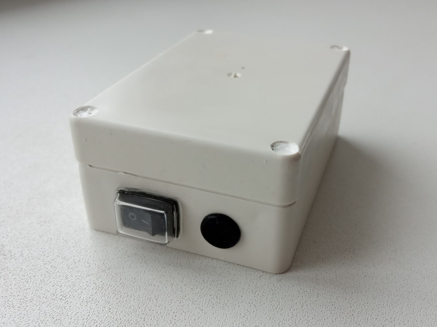
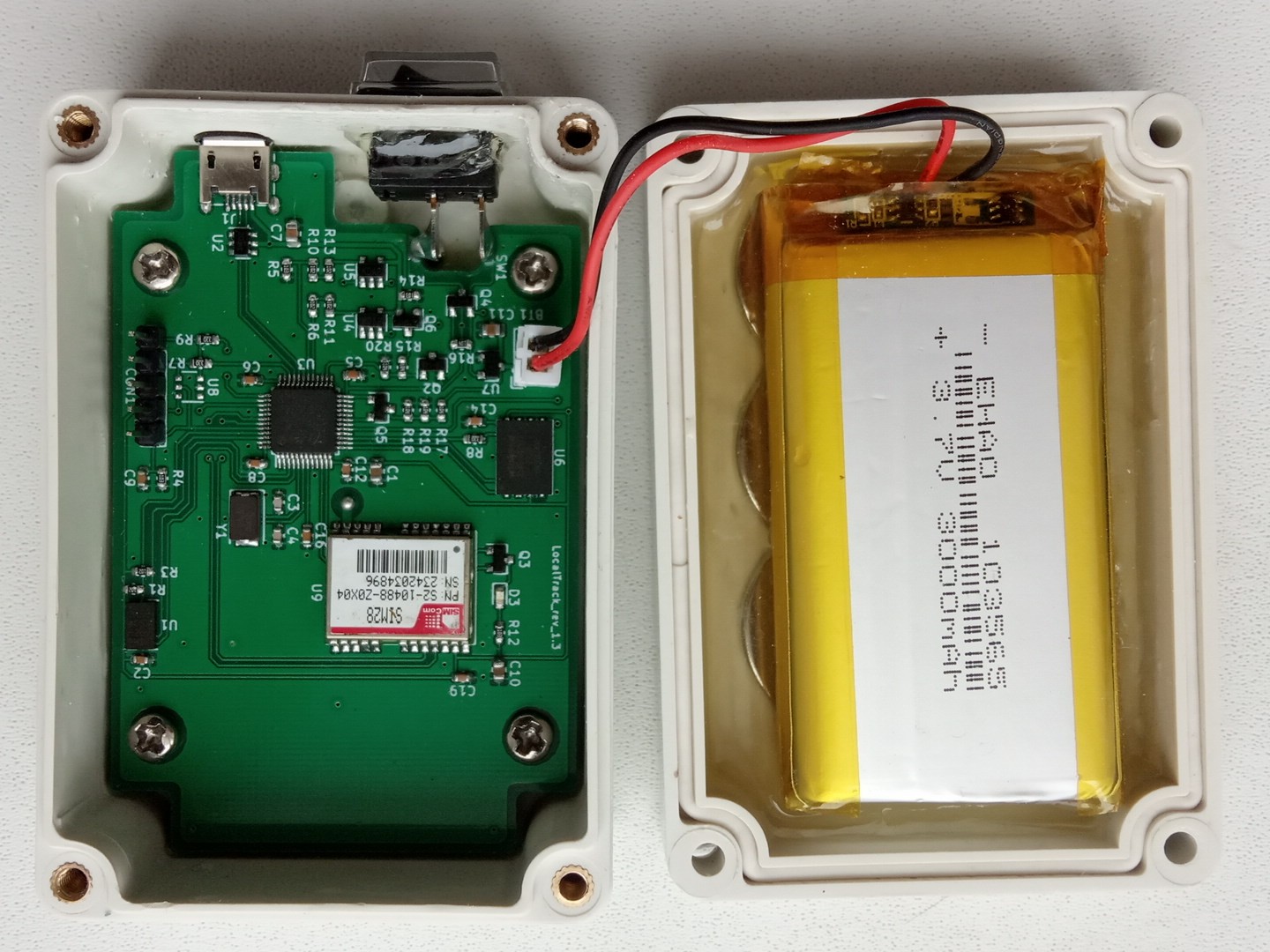
This device is intended for use in applications where real-time tracking is not required,
but other advantages of network-disconnected design are desirable, such as:
No need to pay your cellular service provider.
Local file storage, so you don't have to trust your data to some proprietary
manufacturer's software or depend on a particular service being provided.
Logger is harder to detect; if discovered, it is hard to trace where it came from,
as it does not have information like IMEI, IMSI, payment history, etc. linked to it.
Less power consumption and longer battery life.
CHECK THE WIKI FOR HOW-TO-USE INFORMATION
Project is designed using KiCad 6.0.11
Check KiCad pcb file for PCB manufacturing info
Check KiCad sch file + BOM.txt for component info
Uses integrated full-speed (12Mbit/s) USB2.0 peripheral, with
96MiB of available on-board flash memory for data storage;
measured speeds for MSD access: read 800-850 KiB/s, write 700-750 KiB/s
Fully assembled unit has dimensions of 85x55x32mm and weight of 175 grams.
Hardware programmer device used in this project is ST-Link V2
SIM28 may come in several variants which have different USART speeds by default.
Firmare here expects 9600 baudrate version. If you have different module version
you will need to modify USART1 configuration in main.c and peripherals.c files.
Device has a 3000mAh li-po battery and can function with battery voltage above 3V.
If lower voltage is detected, device enters low battery mode and waits until
the battery is recharged. Current consumption while tracking is around 40mA;
while waiting in sleepmode (eg. due to lack of movement) it is less than 1mA.
This results in about 70 hours of active tracking before battery is depleted.
Battery can be charged via USB with up to 1A of current, so make sure to pick
capable charging adapter and USB cable. Also, keep in mind that you will need
a cable with extra long 8mm micro USB plug, instead of the usual 5.4mm plug.
Programming language used = C
Flashing software used = openocd 0.12.0
IDE used = emacs text editor + Makefile
The firmware was developed on debian 11.3 system, using gcc-arm-none-eabi
toolchain (compiler, linker, binutils) and it does use gcc specific extentions.
it was successfully compiled and tested with arm-none-eabi-gcc version 12.2.1
Depends on libgcc.a, which is included in this repository. Linker script,
startup code and openocd configuration files are included here as well.
For easy in-field updates, you can use the DFU bootloader. There is a dfu
firmware image available in /firmware/firmware_RRNNN.dfu file. The name
format is this: RR stands for board revision (13 = rev 1.3) , NNN stands
for firmware version. For example, firmware_13001.dfu means board
revision 1.3, firmware version 1
To automate firmware build process you can use make utility. If you
open terminal in /firmware/ directory, you could run these commands:
make
make upload
make dfu
make clean
"make" will compile source code and create several files, among them
is firmware.bin which contains firmware to flash. "make upload" will
flash this file via St-Link V2 programmer. Make sure to connect the
programmer to the board properly, before you plug it into PC and run the
command. "make dfu" will create a DFU firmware image from firmware.bin
which can be used later by DFU flashing software. "make clean" will
delete all the compiled or temporary files created by previous commands.
/firmware/cmsis/ ------- header files from CMSIS compliant STM32F0xx standard peripherals library
/firmware/stdlib/ ---------- standard statically linked libraries (libgcc.a)
/firmware/openocd/ ------- standard configuration files for openocd 0.12.0
/firmware/fatfs/ ---------- chan fatfs filesystem module + W25N01GVZEIG disk driver
/firmware/usb/ ------------ USB system and MSD class device implementation
/firmware/main/ ------- main application files, interrupt vector table, IRQ handlers and startup code
/firmware/dfuse-pack.py ------- python script to create .dfu firmware images
/firmware/linkScript.ld ------- custom linker script for the GNU linker (ld)
/firmware/Makefile ------- file used by GNU make utility for build automation
/firmware/firmware_13NNN.dfu ------ pre-compiled firmware image in DfuSe format (STM32)
/hardware/LocalTrack.symbols/ ---- project specific symbol library
/hardware/LocalTrack.pretty/ ----- project specific footprint library
/hardware/gerbers/ ----------- gerber+excellon fabrication output files
/hardware/BOM.txt --------- list of parts and accessories needed for DIY assembly
/mechanical/drawings/ ---- mechanical drawings for some of the parts
/mechanical/KH-F20.FCStd --- freecad model for the plastic enclosure
/extra/photos/ ---------------- photos of the device
/extra/wiki/ ------------------ github wiki pages
if you have a problem / question / feature request, here are your options for contacting me:
send me an email to krakrukra@tutanota.com
create a new github issue (check closed issues first)
also, you can check out my youtube channel
For extra security, you could use my PGP public key saved in /extra/pubkey.asc.
| Qty | Value | Footprint | References |
|---|---|---|---|
| 9 | 100nF | Capacitor_SMD:C_0603_1608Metric | C2, C5, C6, C8, C9, C12, C14, C16, C19 |
| 6 | 100k | Resistor_SMD:R_0603_1608Metric | R15, R16, R17, R18, R19, R20 |
| 6 | 1k | Resistor_SMD:R_0603_1608Metric | R1, R3, R6, R10, R11, R13 |
| 5 | 10k | Resistor_SMD:R_0603_1608Metric | R2, R4, R5, R12, R14 |
| 4 | 10uF | Capacitor_SMD:C_0805_2012Metric | C1, C7, C10, C11 |
| 4 | SI2302 | Package_TO_SOT_SMD:SOT-23 | Q1, Q2, Q3, Q5 |
| 3 | 33 | Resistor_SMD:R_0603_1608Metric | R7, R8, R9 |
| 2 | 18pF | Capacitor_SMD:C_0603_1608Metric | C3, C4 |
| 2 | MCP73831T-2DCI | Package_TO_SOT_SMD:SOT-23-5 | U4, U5 |
| 2 | SI2301 | Package_TO_SOT_SMD:SOT-23 | Q4, Q6 |
| 1 | 1575R-A | LocalTrack:1575R-A | AE2 |
| 1 | 3000mAh | Connector_JST:JST_PH_B2B-PH-K_1x02_P2.00mm_Vertical | BT1 |
| 1 | 8MHz | Crystal:Crystal_SMD_5032-2Pin_5.0x3.2mm | Y1 |
| 1 | ADXL345BCCZ | Package_LGA:LGA-14_3x5mm_P0.8mm_LayoutBorder1x6y | U1 |
| 1 | BLUE | LED_SMD:LED_0603_1608Metric | D3 |
| 1 | GREEN | LED_SMD:LED_0603_1608Metric | D1 |
| 1 | IP4220CZ6 | Package_SO:TSOP-6_1.65x3.05mm_P0.95mm | U2 |
| 1 | KCD11-2P | LocalTrack:KCD1-11 | SW1 |
| 1 | MCP1700-3302E/TT | Package_TO_SOT_SMD:SOT-23 | U7 |
| 1 | RED | LED_SMD:LED_0603_1608Metric | D2 |
| 1 | SIM28 | LocalTrack:SIM28 | U9 |
| 1 | ST-LINK_V2 | Connector_PinHeader_2.54mm:PinHeader_1x05_P2.54mm_Vertical | CON1 |
| 1 | STM32F072C8T6 | Package_QFP:LQFP-48_7x7mm_P0.5mm | U3 |
| 1 | USB_B_Micro | LocalTrack:MicroUSB_B | J1 |
| 1 | W25N01GVZEIG | LocalTrack:WSON-8_8x6mm | U6 |
| 1 | test pins | LocalTrack:TestPins | TP1 |
The 59 most common of 63 parts.

giant-axon/lu.i-neuron-pcb
Lu.i is an electronic neuron circuit mimicking and illustrating the basic dynamics of real, biological neurons. The printed circuit board (PCB) features a configurable, fully analog implementation of the leaky…

ayuusweetfish/Malletwand
A pendulum as a hands-on musical interface for all · NIME 2024 Short Paper

trieuhuyduc/Clean_room_slave
ESP32-based slave controller board for cleanroom equipment — RS485/Modbus, isolated I/O, 220V mains control (KiCad)


Appiko/sense_snap_hw
This repository contains all the KiCad based PCB design and related documentation for all the PCBs developed at Appiko.


henrikssn/TurboCAN
This is the official repository for the TurboCAN controller board, designed specifically for the Voron AfterBurner toolhead but can also be used on similar toolheads using NEMA17 steppers.
It measures 50 × 75 mm and has 2 copper layers, 0.89 mm thick.
63 parts, built around the STM32F072C8T6, W25N01GVZEIG, ADXL345BCCZ and IP4220CZ6. The full list of its parts is on this page, with links to each part's symbol and footprint where PCBKit's library has them.
From the krakrukra/LocalTrack repository on GitHub, at the commit this page was made from: the board is hardware/LocalTrack.kicad_pcb and its schematic hardware/LocalTrack.kicad_sch. PCBKit opens the board in the browser, with nothing to install.
Its repository publishes it under the MIT licence: you may reuse it on that licence's terms (keep the author's notice, and for a copyleft licence share your changes alike).