2 layers215 × 83 mm
Kino key25
kinoshita-lab/kino-key
Open source piano-type keyboard MIDI controller project
125 parts6MIT

 kinoshita-lab/MIDI-UART-interface-san20
Handy interface PCB for MIDI and microcontrollers.
MIDI UART interface san is an open-source printed circuit board by kinoshita-lab, from the kinoshita-lab/MIDI-UART-interface-san repository on GitHub. It is a 2-layer board of 56 × 32 mm with 37 parts on 27 nets, routed with 271 tracks and 34 vias.
It is built around the TLP2361(TPL,E, 19-213/Y2C-CQ2R2L/3T(CY) and 19-217/GHC-YR1S2/3T, with the KT-0603R and SM4007PL among its other parts. Its parts include 10 resistors, 5 connectors, 4 diodes, 3 capacitors and 3 ICs. It belongs with the interfaces and adapters and audio and music boards of this library.


MIDI UART interface-san is a handy interface PCB for MIDI and microcontrollers with commonly used basic circuit when you start developping MIDI-related MCU project, e.g. TRS jacks for MIDI I/O, optocouplers, digital buffers, etc. It means by using this PCB, you do not have to repeat soldering/making a breadboard for these purpose anymore.
You can choose both 5V and 3.3V for power supply(can be selected jumper pins), to match the voltage of the MCU you want to use.
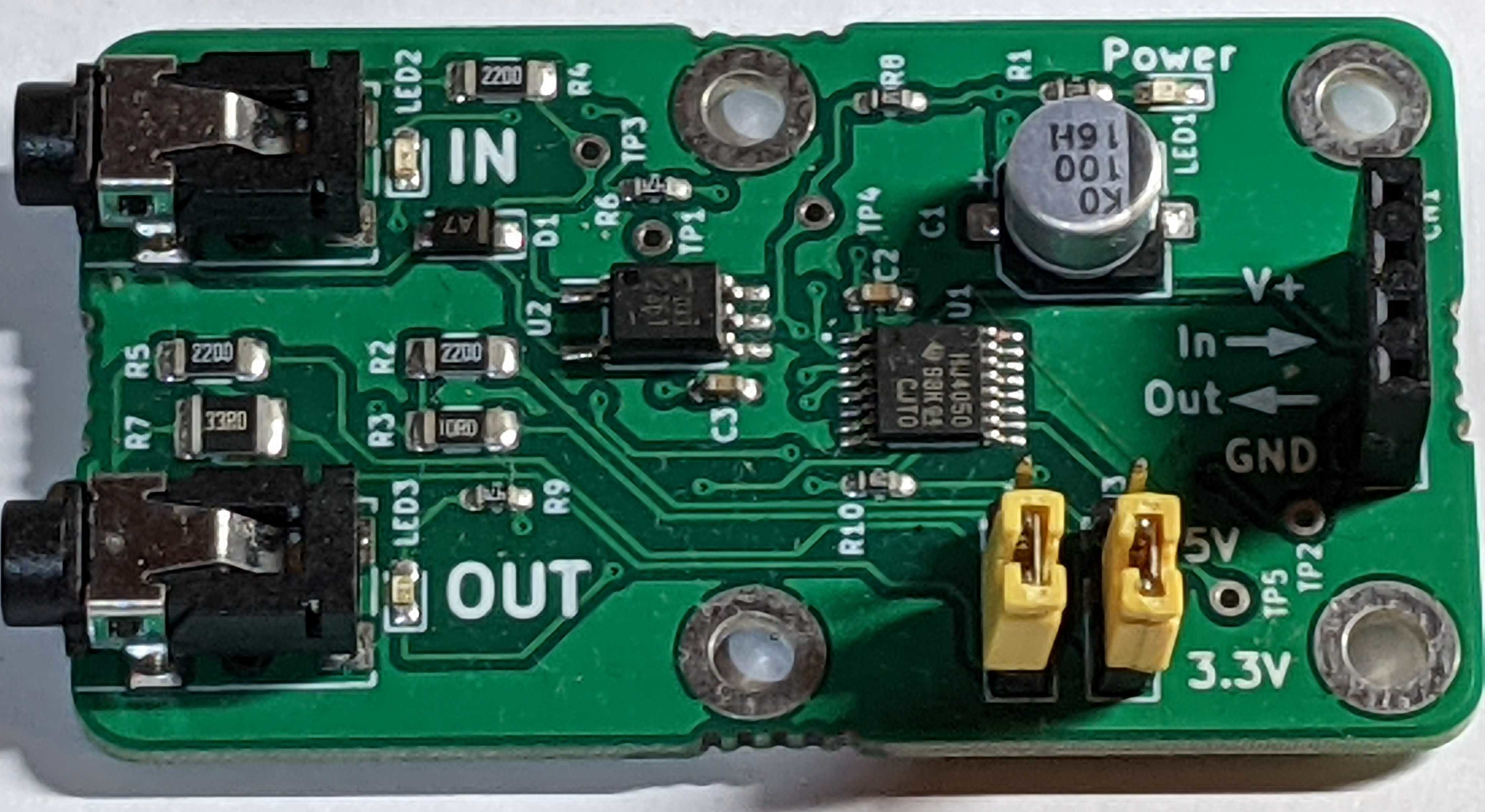
Solder all of the jacks and connectors on the circuit board.
Please refer to the following image.
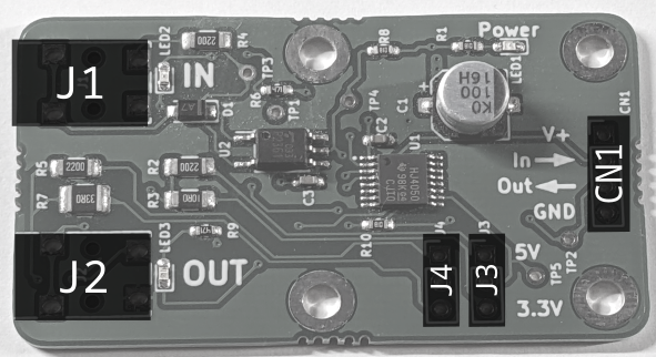
In-> to the MCU's MIDI Input.Out-> to the MCU's MIDI Output.| Qty | Value | Footprint | References |
|---|---|---|---|
| 5 | TestPoint | my_footprint:TP_1PAD | TP1, TP2, TP3, TP4, TP5 |
| 4 | MountingHole_Pad | MountingHole:MountingHole_3.2mm_M3_ISO7380_Pad | H1, H2, H3, H4 |
| 3 | 220 | Resistor_SMD:R_1206_3216Metric_Pad1.30x1.75mm_HandSolder | R2, R4, R5 |
| 2 | my_footprint:yajirushi-800dpi_3_6x1_3mm | , | |
| 2 | 0.1u | Capacitor_SMD:C_0603_1608Metric_Pad1.08x0.95mm_HandSolder | C2, C3 |
| 2 | 1k | Resistor_SMD:R_0603_1608Metric_Pad1.05x0.95mm_HandSolder | R1, R10 |
| 2 | 470 | Resistor_SMD:R_0603_1608Metric_Pad1.05x0.95mm_HandSolder | R6, R9 |
| 2 | Conn_01x03_Female | Connector_PinHeader_2.54mm:PinHeader_1x03_P2.54mm_Vertical | J3, J4 |
| 1 | 10 | Resistor_SMD:R_1206_3216Metric_Pad1.30x1.75mm_HandSolder | R3 |
| 1 | 100u 6.3V | Capacitor_SMD:C_1206_3216Metric_Pad1.33x1.80mm_HandSolder | C1 |
| 1 | 19-213/Y2C-CQ2R2L/3T(CY) | LED_SMD:LED_0603_1608Metric_Pad1.05x0.95mm_HandSolder | LED2 |
| 1 | 19-217/GHC-YR1S2/3T | LED_SMD:LED_0603_1608Metric_Pad1.05x0.95mm_HandSolder | LED3 |
| 1 | 1k | Resistor_SMD:R_0603_1608Metric_Pad0.98x0.95mm_HandSolder | R8 |
| 1 | 33 0.5W | Resistor_SMD:R_1210_3225Metric_Pad1.30x2.65mm_HandSolder | R7 |
| 1 | AudioJack3 | MIDI-Interface-san:3.5mm_Stereo_TRS_PJ-3210-4A_and_ST-005-G | J2 |
| 1 | AudioJack3 | my_footprint:3.5mm_Stereo_TRS_PJ-3210-4A_and_ST-005-G | J1 |
| 1 | BAS40DW-04-7-F | ultra_librarian:SOT-363_DIO | U3 |
| 1 | CD74HC4050PWR/74HC4050PW | MIDI-Interface-san:SOP65P640X120-16N | U1 |
| 1 | Conn_01x04_Female | Connector_PinHeader_2.54mm:PinHeader_1x04_P2.54mm_Vertical | CN1 |
| 1 | KT-0603R | LED_SMD:LED_0603_1608Metric_Pad1.05x0.95mm_HandSolder | LED1 |
| 1 | LOGO | my_footprint:kinoshita-logo-300dpi | G*** |
| 1 | SM4007PL | Diode_SMD:D_SOD-123 | D1 |
| 1 | TLP2361_TPL_E | Package_SO:SO-5_4.4x3.6mm_P1.27mm | U2 |
kinoshita-lab/kino-key
Open source piano-type keyboard MIDI controller project

elagil/net-bmp
An Ethernet-connected SWD/JTAG debug adapter (blackmagic probe)


ConnorRigby/GD32-Devboard
Simple GD32F405 Development board with CAN, SD Card, Lora, BLE and GPS


It measures 56 × 32 mm and has 2 copper layers, 1.6 mm thick.
37 parts, built around the TLP2361(TPL,E, 19-213/Y2C-CQ2R2L/3T(CY), 19-217/GHC-YR1S2/3T and KT-0603R. The full list of its parts is on this page, with links to each part's symbol and footprint where PCBKit's library has them.
From the kinoshita-lab/MIDI-UART-interface-san repository on GitHub, at the commit this page was made from: the board is MIDI-UART-Interface-san.kicad_pcb and its schematic MIDI-UART-Interface-san.kicad_sch. PCBKit opens the board in the browser, with nothing to install.
Its repository states no licence, so its author keeps all rights: ask kinoshita-lab before reusing the design.