
2 layers63 × 46 mm
Pi485
bvarner/pi485
An open-source TTL UART <-> RS485 converter, intended for a Raspberry Pi or Arduino
31 parts41MIT

 kellertobias/magic-cueboard2
This tool is used in combination with a MagicQ light control desk to extend the amount of physical buttons on the desk.
DMX MIDI FIGHTER is an open-source printed circuit board by kellertobias, from the kellertobias/magic-cueboard repository on GitHub. It is a 2-layer board of 235 × 171 mm with 149 parts on 118 nets, routed with 1,092 tracks and 447 vias.
It is built around the MAX485ED. Its parts include 41 diodes, 41 switches, 40 capacitors, 18 resistors and 4 connectors. It belongs with the audio and music boards of this library.
This tool is used in combination with a MagicQ light control desk to extend the amount of physical buttons on the desk.
It communicates via OSC to MagicQ and uses its HTTP API to update the available executors. It also interfaces with a gm1356 based SPL meter to display a little graph of how much the current DJ destroys your ears.
! This project is written by AI in large parts (as an experiment how far you can push it). That's why the code might not be super clean. The project however is fully functional and has been used to control lights for a few events.
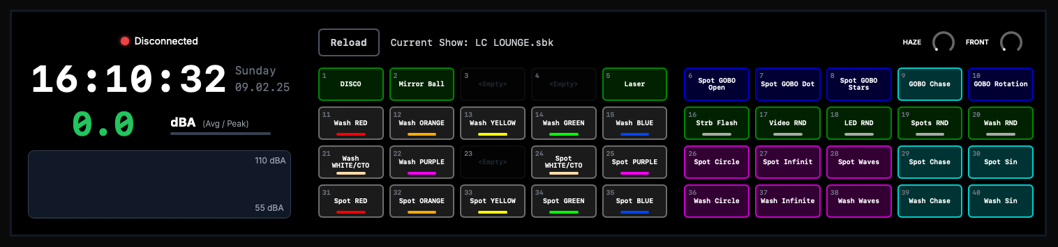
light-assistant/
├── hardware/ # Hardware specific code and PCB schematics
├── src/
│ ├── app/ # NextJS frontend code
│ ├── components/ # React components
│ ├── contexts/ # React contexts
│ ├── hooks/ # React hooks
│ ├── mocks/ # Mock implementations of the interfacing systems to test against
│ ├── websocket-server/ # The Server to interface with the external systemsnpm install to install the dependenciesnpm run dev to start the development server(s)You might want to run this on a raspberry PI and set it up so that it automatically starts when the pi starts and then opens the browser to the local webserver.
AAA,T,FF0 for a gray toggle button with a yellow icon)The Raspberry Pi server also accepts the original MagicQ source setting for compatibility:
# Local MagicQ compatibility: the Pi reads MagicQ directly and discovers its
# attached Cueboard by USB ID.
MAGICQ_SOURCE=self

# Windows mode: the ToskLight Windows hardware bridge owns MagicQ and the USB board.
MAGICQ_SOURCE=windows
WINDOWS_MAGICQ_WS_URL=ws://10.99.0.1:47872/surface
WINDOWS_MAGICQ_TOKEN=tosklight-magicq-feed-v1
auto is the default. In windows mode the Pi keeps serving its local UI, SPL meter, and MQTT data, while executor names, colours, types, and live values come from Windows. The dot colour is inferred from whole colour words in the MagicQ executor name, including Red, Orange, Yellow, Green, Blue, Cyan, CTO, White, Amber, Magenta, Purple, Pink, and UV.
The preferred deployment now uses a selectable surface source:
# Automatic mode (default): the Windows bridge selects MagicQ whenever it is
# running, otherwise ToskLight, otherwise the waiting screen.
SURFACE_SOURCE=auto

# MagicQ on the Windows show computer. Buttons travel back over the same
# authenticated WebSocket and Windows uses MagicQ Remote (CHWP), not OSC.
SURFACE_SOURCE=windows
WINDOWS_MAGICQ_WS_URL=ws://10.99.0.1:47872/surface
WINDOWS_MAGICQ_TOKEN=tosklight-magicq-feed-v1

# ToskLight on the Windows show computer. The Pi reads page/show metadata
# through its operator session and sends physical Cueboard actions to the bridge.
SURFACE_SOURCE=tosklight
TOSKLIGHT_API_URL=http://10.99.0.1:5000
WINDOWS_MAGICQ_WS_URL=ws://10.99.0.1:47872/surface
MAGICQ_SOURCE=self|windows remains accepted for existing installations. SURFACE_SOURCE takes precedence and supports auto|self|windows|tosklight. In automatic mode the Pi can boot before the Windows computer; both the Windows surface connection and the ToskLight API retry after boot, disconnects, and restarts. MagicQ always has priority.
Set SPL_API_URL to a JSON endpoint to display a network SPL meter instead of the local splread binary. Native { "measured": 91.2, "freqMode": "dBA" }, simple { "value": 91.2 }, and Home Assistant { "state": "91.2", "attributes": { "unit_of_measurement": "dBA" } } responses are accepted. SPL_API_INTERVAL_MS controls polling and defaults to 250 ms.
Every reading is also published by the Pi's MQTT broker on port 1883. Existing consumers can continue using retained spl/value and spl/mode. New consumers should subscribe to retained tosklight/spl for the complete JSON measurement, or tosklight/spl/value, tosklight/spl/unit, tosklight/spl/timestamp, and tosklight/spl/availability for individual fields. Availability is online while readings are being published and changes to offline during a clean shutdown.
The executor layout can be changed in the on-screen Settings panel and is persisted across restarts. EXECUTOR_LAYOUT=legacy|new selects the initial value on a new installation (compact remains accepted as an alias for new):
legacy: buttons use MagicQ rows 1, 3, 5, and 7; rows 2, 4, 6, and 8 contain each button's colour/type configuration; the two potentiometers use items 81 and 82.new: buttons use every row and take their colour, Toggle/Flash/Solo type, region, active state, and fader metadata directly from Execute Page 1. The two potentiometers control the first two fader items on the page.
In both layouts the live Remote grid supplies button text and active state. Legacy mode preserves the existing paired name/configuration rows; New mode gets colour, button type, region and fader properties directly from the selected API or MagicQ Remote metadata.The Cueboard is attached to the Raspberry Pi. On Linux, Magic Qboard discovers only its Leonardo USB ID 2341:8037, so the SPL meter or another serial device cannot be mistaken for the board. BUTTON_CONTROLLER_PORT can pin a known port if needed. On Windows, local serial discovery stays off unless a port is explicitly set. All physical Cueboard button and fader actions travel from the Pi through the authenticated Windows bridge, which routes them to MagicQ or ToskLight according to its current owner. MagicQ feed and ToskLight API snapshots provide live values and colours to drive the Pi board LEDs. The UI remains visible while the board or Windows reconnects.
Alternatively the PCB also supports Hardware MIDI out (not tested yet) or DMX out (tested and works)
when you have flashed the USB Midi version and press the top left button while powering it up, you can select the colors and brightness of the buttons' backlight. In the USB Custom version, the buttons' backlights are controlled by the server application and the DMX out of the board is disabled. In this mode it only interfaces with this project.
This project was an experiment to see how far you could push an AI to write an entire application. It started from an empty folder and the following prompt:
Install https://github.com/yoggy/sendosc
and then
sendosc 192.168.42.147 8000 /exec/1/12 f 0.6| Qty | Value | Footprint | References |
|---|---|---|---|
| 41 | D_Small_Filled | Diode_SMD:D_SOD-323 | D1, D2, D10, D11, D12, D13, D14, D15, D16, D17, D18, D19, D20, D21, D22, D23 +25 |
| 40 | C_Small | Capacitor_SMD:C_0805_2012Metric | C1, C2, C10, C11, C12, C13, C14, C15, C16, C17, C18, C19, C20, C21, C22, C23 +24 |
| 40 | Switch_SW_WS2812B | Button_Switch_Keyboard:Cherry_MX_SK6812_BS | SW1, SW2, SW10, SW11, SW12, SW13, SW14, SW15, SW16, SW17, SW18, SW19, SW20, SW21, SW22, SW23 +24 |
| 8 | 10k | Resistor_SMD:R_0805_2012Metric_Pad1.20x1.40mm_HandSolder | R6, R7, R8, R9, R10, R11, R12, R13 |
| 5 | 100 | Resistor_SMD:R_0805_2012Metric_Pad1.20x1.40mm_HandSolder | R1, R2, R3, R4, R5 |
| 3 | 220 | Resistor_THT:R_Axial_DIN0411_L9.9mm_D3.6mm_P12.70mm_Horizontal | R14, R15, R16 |
| 2 | R_Potentiometer | Potentiometer_THT:Potentiometer_Alps_RK09K_Single_Vertical | RV1, RV2 |
| 1 | 10k | Resistor_THT:R_Axial_DIN0411_L9.9mm_D3.6mm_P12.70mm_Horizontal | R18 |
| 1 | 470 | Resistor_THT:R_Axial_DIN0411_L9.9mm_D3.6mm_P12.70mm_Horizontal | R17 |
| 1 | 6N138 | Package_DIP:DIP-8_W7.62mm | U3 |
| 1 | Conn_01x02_Pin | Connector_PinHeader_2.54mm:PinHeader_1x02_P2.54mm_Vertical | J7 |
| 1 | Conn_01x03_Pin | Connector_PinHeader_2.54mm:PinHeader_1x03_P2.54mm_Vertical | J8 |
| 1 | Conn_01x03_Pin | Button_Switch_THT:SW_CK_JS202011AQN_DPDT_Angled | J5 |
| 1 | MAX485E | Package_SO:SOIC-8_3.9x4.9mm_P1.27mm | U2 |
| 1 | SW_Push | Button_Switch_THT:SW_Tactile_SPST_Angled_PTS645Vx58-2LFS | SW41 |
| 1 | XLR3 | Connector_Audio:Jack_XLR_Neutrik_NC3FAH1-0_Horizontal | J3 |
| 1 | ~ | Module:Arduino_PRO_MIcro_USB-C | U1 |
It measures 235 × 171 mm and has 2 copper layers, 1.6 mm thick.
149 parts, built around the MAX485ED. The full list of its parts is on this page, with links to each part's symbol and footprint where PCBKit's library has them.
From the kellertobias/magic-cueboard repository on GitHub, at the commit this page was made from: the board is hardware/kicad/DMX_MIDI_FIGHTER.kicad_pcb and its schematic hardware/kicad/DMX_MIDI_FIGHTER.kicad_sch. PCBKit opens the board in the browser, with nothing to install.
Its repository states no licence, so its author keeps all rights: ask kellertobias before reusing the design.
bvarner/pi485
An open-source TTL UART <-> RS485 converter, intended for a Raspberry Pi or Arduino


GrappleRobotics/JMS
Another alternative field management system for the FIRST Robotics Competition.

StefanKrupop/XyloShield
Shield for Arduino that hosts a RFM26W radio module and allows DMX-512 connectivity

SylvainVanIniitu/Piccolo-4C-Black
Piccolo MIDI stochastic sequencer

ChaseDurand/Pool-Pi
Hardware+software solution for controlling a Goldline/Hayward Aqualogic pool control board over WiFi via a Raspberry Pi.

flxkrmr/eec-iv-reader-arduino
Arduino based diagnostics-tool for Fords EEC IV ECUs