


2 layers70 × 30 mm
Pi485bearer
bvarner/pi485
An open-source TTL UART <-> RS485 converter, intended for a Raspberry Pi or Arduino
25 parts41MIT

 bvarner/pi48541
An open-source TTL UART <-> RS485 converter, intended for a Raspberry Pi or Arduino
Pi485 is an open-source printed circuit board by bvarner, from the bvarner/pi485 repository on GitHub, published under the MIT licence. It is a 2-layer board of 63 × 46 mm with 31 parts on 22 nets, routed with 219 tracks and 0 vias.
It is built around the MAX485ED, RS485 and NE555, with the BAT43 among its other parts. Its parts include 12 resistors, 5 connectors, 4 capacitors, 4 diodes and 4 transistors. It belongs with the interfaces and adapters boards of this library.


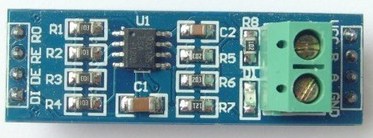
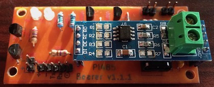
Based upon what I learned while creating the Standalone pi485, this board is meant to function as a carrier / bearer for an LC Technologies RS485 module, adding the RX / TX LEDs, power controll, and latched DE / RE pin driving to this very inexpensive and commonly available module.
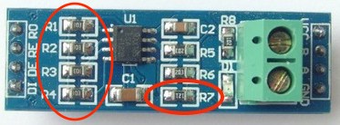
Unlike the standalone board this layout prioritizes compactness over ease of use for beginners. The trace clearances are tighter and you'll need to remove five surface mount resistors from the RS485 module. In practice, I've found these boards are reasonably easy to produce with a laser printer hot iron transfer.
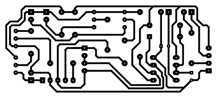
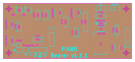
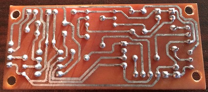
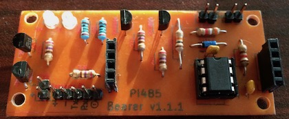
is designed to hold these RS485 modules
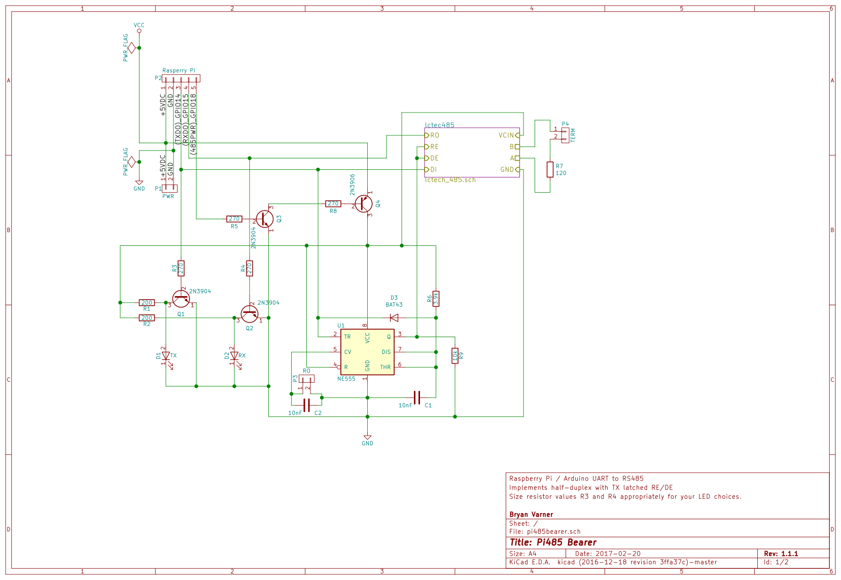
For in-depth details on the function of the circuit refer to the Standalone Module README.
| Qty | Value | Footprint | References |
|---|---|---|---|
| 4 | 270 | Resistors_THT:Resistor_Horizontal_RM10mm | R8, R9, R10, R11 |
| 3 | 2N3904 | TO_SOT_Packages_THT:TO-92_Inline_Wide | Q1, Q2, Q3 |
| 2 | 200 | Resistors_THT:Resistor_Horizontal_RM10mm | R3, R7 |
| 2 | 20k | Resistors_THT:Resistor_Horizontal_RM7mm | R4, R6 |
| 1 | 0.1uF | Capacitors_THT:C_Rect_L7_W2.5_P5 | C2 |
| 1 | 10k | Resistors_THT:Resistor_Horizontal_RM7mm | R12 |
| 1 | 10nF | Capacitors_THT:C_Rect_L7_W2.5_P5 | C3 |
| 1 | 10nF | Capacitors_THT:C_Rect_L4_W2.5_P2.5 | C4 |
| 1 | 10uF | Capacitors_THT:C_Radial_D5_L11_P2 | C1 |
| 1 | 120 | Resistors_THT:Resistor_Horizontal_RM10mm | R5 |
| 1 | 200 | Resistors_THT:Resistor_Horizontal_RM7mm | R1 |
| 1 | 2N3906 | TO_SOT_Packages_THT:TO-92_Inline_Wide | Q4 |
| 1 | 3.9k | Resistors_THT:Resistor_Horizontal_RM10mm | R2 |
| 1 | BAT43 | Diodes_THT:Diode_DO-35_SOD27_Horizontal_RM10 | D4 |
| 1 | MAX485 | Housings_DIP:DIP-8_W7.62mm_LongPads | U2 |
| 1 | NE555 | Housings_DIP:DIP-8_W7.62mm_LongPads | U1 |
| 1 | PWR | LEDs:LED-3MM | D1 |
| 1 | PWR | Pin_Headers:Pin_Header_Straight_1x02 | P2 |
| 1 | RO | Pin_Headers:Pin_Header_Straight_1x02 | P4 |
| 1 | RS485 | Connectors_Terminal_Blocks:TerminalBlock_Pheonix_MPT-2.54mm_2pol | J1 |
| 1 | RX | LEDs:LED-3MM | D3 |
| 1 | Rasperry Pi | Pin_Headers:Pin_Header_Straight_1x05 | P1 |
| 1 | TERM / BIAS | Pin_Headers:Pin_Header_Straight_2x03 | P3 |
| 1 | TX | LEDs:LED-3MM | D2 |
It measures 63 × 46 mm and has 2 copper layers, 1.6 mm thick.
31 parts, built around the MAX485ED, RS485, NE555 and BAT43. The full list of its parts is on this page, with links to each part's symbol and footprint where PCBKit's library has them.
From the bvarner/pi485 repository on GitHub, at the commit this page was made from: the board is standalone/pi485.kicad_pcb. PCBKit opens the board in the browser, with nothing to install.
Its repository publishes it under the MIT licence: you may reuse it on that licence's terms (keep the author's notice, and for a copyleft licence share your changes alike).
bvarner/pi485
An open-source TTL UART <-> RS485 converter, intended for a Raspberry Pi or Arduino

telagod/moskill
MosKill - Smart Mosquito Swatter with BLE, Kill Counting & Statistics | ESP32-C3 + KiCad PCB + UniApp

clarionut/Scriabin_CV-DMX
A 2-channel CV to DMX converter for use with a modular synthesiser


JCohner/booth
Using 1000 NeoPixels with FastLED library we are controlling a custom built DJ booths lighting. The NeoPixels are organzied into rectangles on a DJ of which the light difuses around the rectnagle.


