2 layers90.2 × 44.4 mm
 crodar33/CommandPoint2
ESP8266, Daly smart bms, HYD6000-ES
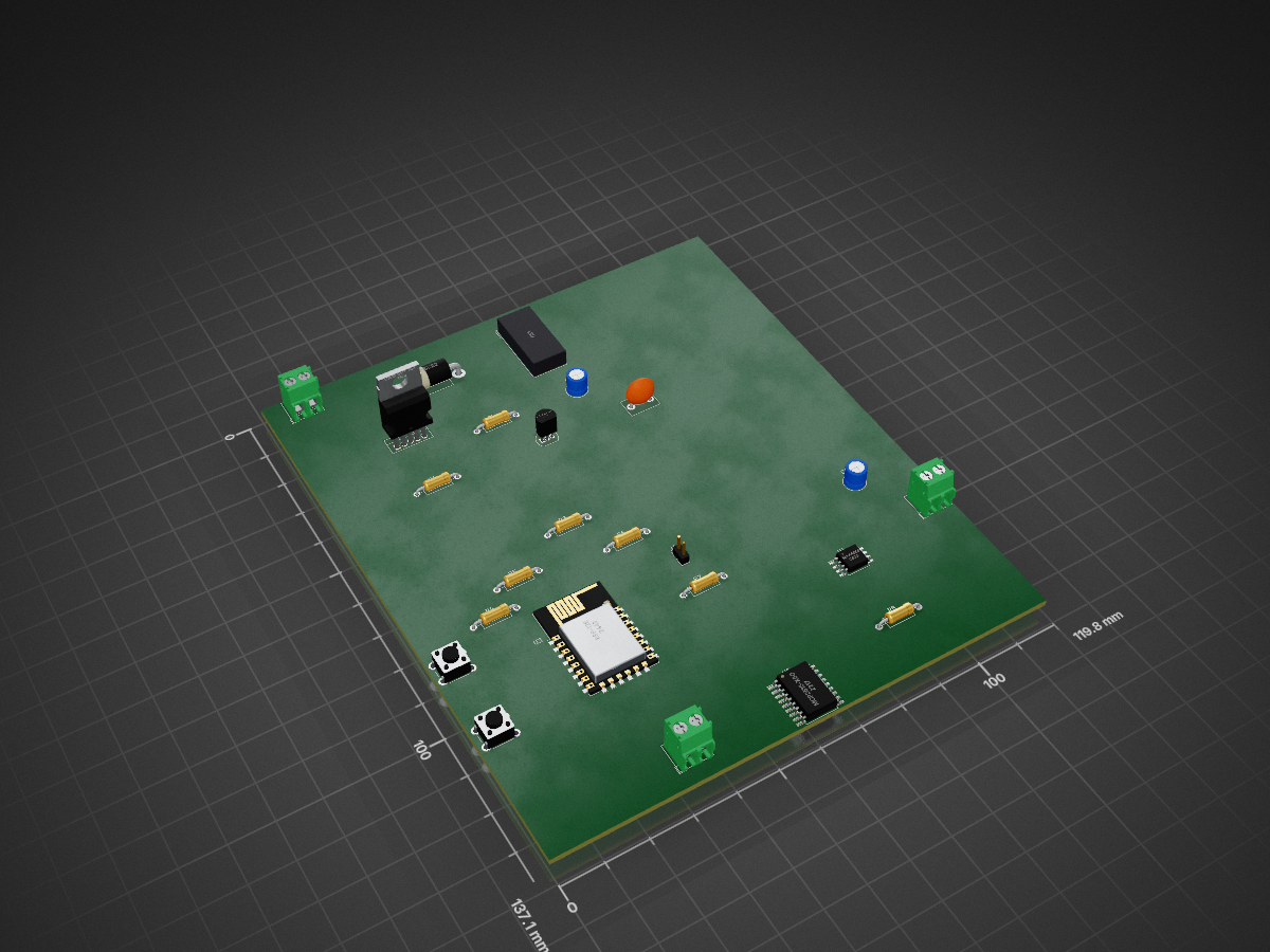
Communication brain is an open-source printed circuit board by crodar33, from the crodar33/CommandPoint repository on GitHub, published under the Apache-2.0 licence. It is a 2-layer board with 24 parts on 40 nets.
It is built around the ESP-12E, MAX485ED and RS485, with the LM2576HVT-ADJ among its other parts. Its parts include 8 resistors, 5 ICs, 4 connectors, 3 capacitors and 2 switches. It belongs with the ESP8266 boards of this library.


Scheme based on ESP8266 for pool data from BSM of the battery with daly smart bms and provide battery data to SOFAR HYBRID inverter HYD6000-ES
They not compatible to each to other, so I need to make middle man for it work together.
In current implementation it can:
Used ESP8266, MCP2515, MAX485 and nodeMCU, code writed on LUA Build nodemcu with I2C_MASTER_GPIO16_ENABLE and without I2C_MASTER_OLD_VERSION LUA_USE_MODULES_SOFTUART LUA_USE_MODULES_STRUCT LUA_USE_MODULES_U8G2
| Qty | Value | Footprint | References |
|---|---|---|---|
| 6 | 10k | Resistor_THT:R_Axial_DIN0207_L6.3mm_D2.5mm_P10.16mm_Horizontal | R3, R4, R5, R6, R7, R8 |
| 1 | 0.1mF | Capacitor_THT:C_Disc_D7.5mm_W5.0mm_P5.00mm | C3 |
| 1 | 1.8k | Resistor_THT:R_Axial_DIN0207_L6.3mm_D2.5mm_P10.16mm_Horizontal | R2 |
| 1 | 1000mF | Capacitor_THT:C_Radial_D5.0mm_H5.0mm_P2.00mm | C2 |
| 1 | 100mF | Capacitor_THT:C_Radial_D5.0mm_H5.0mm_P2.00mm | C1 |
| 1 | 100mH | Inductor_THT:Choke_Schaffner_RN202-04-8.8x18.2mm | L1 |
| 1 | 1N5822 | Diode_THT:D_DO-201AD_P15.24mm_Horizontal | D1 |
| 1 | 5.6k | Resistor_THT:R_Axial_DIN0207_L6.3mm_D2.5mm_P10.16mm_Horizontal | R1 |
| 1 | Batt | TerminalBlock_4Ucon:TerminalBlock_4Ucon_1x02_P3.50mm_Horizontal | J2 |
| 1 | CAN | TerminalBlock_4Ucon:TerminalBlock_4Ucon_1x02_P3.50mm_Horizontal | J4 |
| 1 | ESP-12E | RF_Module:ESP-12E | U3 |
| 1 | L78L33_TO92 | Package_TO_SOT_THT:TO-92_Inline | U2 |
| 1 | LM2576HVT-ADJ | Package_TO_SOT_THT:TO-220-5_Vertical | U1 |
| 1 | MAX485E | Package_SO:SOIC-8_5.23x5.23mm_P1.27mm | U4 |
| 1 | MCP2515-xSO | Package_SO:SOIC-18W_7.5x11.6mm_P1.27mm | U5 |
| 1 | Programm | Button_Switch_THT:SW_PUSH_6mm_H5mm | SW2 |
| 1 | RS485 | TerminalBlock_4Ucon:TerminalBlock_4Ucon_1x02_P3.50mm_Horizontal | J3 |
| 1 | Reset | Button_Switch_THT:SW_PUSH_6mm_H5mm | SW1 |
| 1 | UART | Connector_PinHeader_2.00mm:PinHeader_1x02_P2.00mm_Vertical | J1 |
24 parts, built around the ESP-12E, MAX485ED, RS485 and LM2576HVT-ADJ. The full list of its parts is on this page, with links to each part's symbol and footprint where PCBKit's library has them.
From the crodar33/CommandPoint repository on GitHub, at the commit this page was made from: the board is communication_brain_board/communication_brain.kicad_pcb and its schematic communication_brain_board/communication_brain.kicad_sch. PCBKit opens the board in the browser, with nothing to install.
Its repository publishes it under the Apache-2.0 licence: you may reuse it on that licence's terms (keep the author's notice, and for a copyleft licence share your changes alike).

francesmatthew/BikeLite
This is the schematic and PCB for a buck converter and 555 timer to add flashing LEDs to my bike


saitis-net/sl8500_retrofit_electronics
Kicad projects for the hardware parts

Vihaan6119/RePower
it takes power from a wall adapter via usb-c/dc input and uses a through-hole step down buck regulator (LM2576/LM2596) to convert it to a steady 3.9v dc directly into the speaker's mainboard.

reivax-boucoi/PCB_Kicad
Repo for all my home projects involving PCBs developped with Kicad


bvarner/pi485
An open-source TTL UART <-> RS485 converter, intended for a Raspberry Pi or Arduino