3D-printed, tilted test shelf for 16 dev boards: sliding drawers, per-bay ESP32-S3 running Zephyr (USB/IP, power switching, metering), KiCad PCBs, OpenSCAD parts, BOM and an interactive 3D viewer
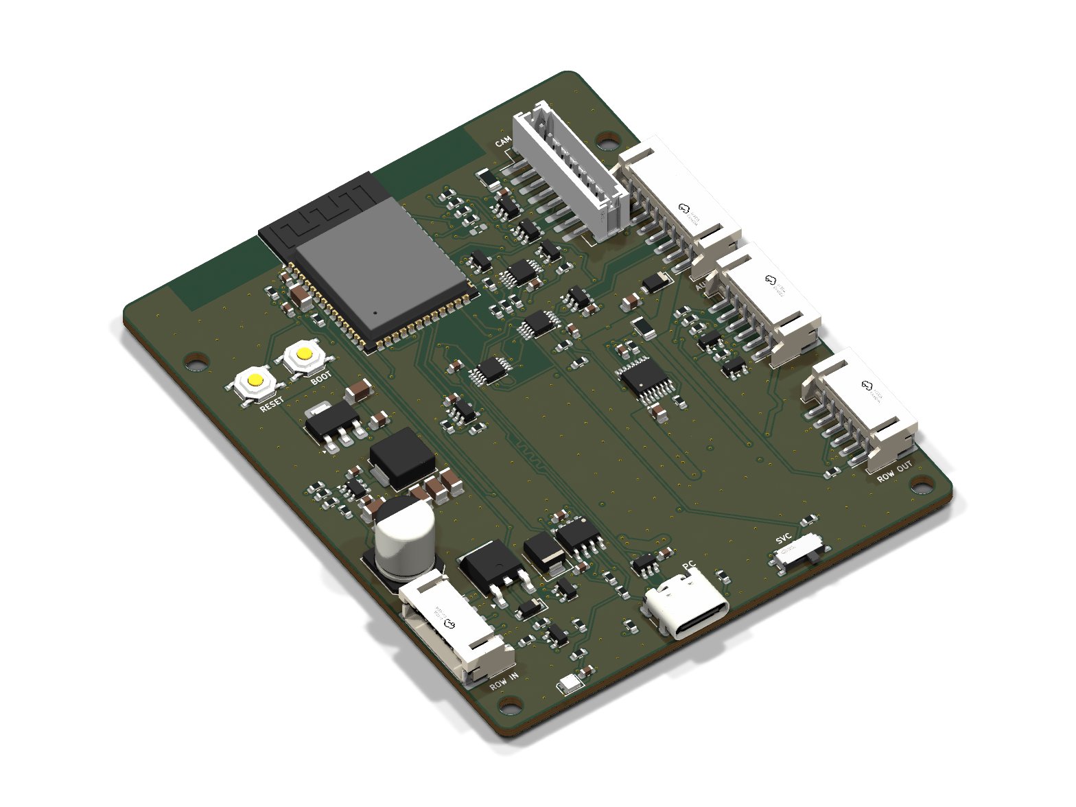
Data port x4 is an open-source printed circuit board by kartben, from the kartben/hw-testing-rack repository on GitHub. It is a 4-layer board of 100 × 70 mm with 290 parts on 391 nets, routed with 3,456 tracks and 894 vias.
It is built around the RP2350B, INA226AIDGSR and USB2517I-JZX, with the H5VU25UC, LSF0108RKSR and TPS2553DBVR-1 among its other parts. Its parts include 86 resistors, 75 capacitors, 44 ICs, 10 connectors and 5 diodes. It belongs with the RP2350 boards of this library.
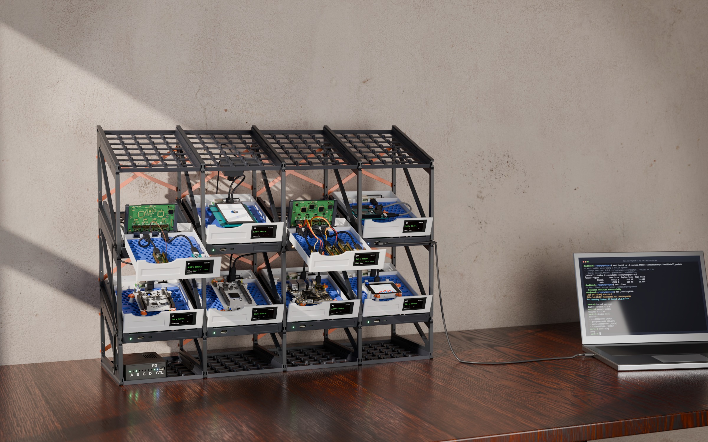
An all-printed, tilted test rack for development boards (12 in its default
4 × 3 layout) — every board in its own sliding drawer, power-switched,
current-metered and exposed over the network with USB/IP by a Zephyr-powered
ESP32-S3 in each bay.
Printed panel frame, no aluminium — side walls ("ladders") shared by
neighbouring bays, stacked row on row with snap hooks; trays slide into
their grooves and click in; a taut X brace behind every bay keeps it square.
Rows tilt 20° so every board, LED and label faces you, and the grid grows
in both directions.
Drawers that stay connected — each bay is a drawer sliding 140 mm along
the slope; a drag chain hidden in the floor carries the cable, so you can
pull a board out to probe it while it keeps running.
One plate for every board — a honeycomb plate in each drawer; clip-in
pegs (stops, cams, pins) hold any board on it, placed by a tool from a small
board library (UNO, Nucleo-64/144, Pico, nRF DKs, FRDM, …): up to four small
boards on one plate.
One ESP32-S3 per bay — switches the board's 5 V (current-limited,
default on), measures V/I (INA226), drives UART/RESET/BOOT lines, and
exports the board's USB with Zephyr's USB/IP host service. Plug a laptop
into the bay's front port and the USB data path switches to it — the
"classic" way still works, even with no firmware.
One USB-C charger — a printed power box under the first column holds
the hub: a USB PD 3.1 sink (20 or 28 V from one charger, no mains in the
rack) and an eFuse per row; a 60 V-rated buck in every bay. The same row
cables carry a CAN bus for the rack controller (can.md).
Cameras — an optional Arducam Mega (SPI, ~120° M12 lens) and white LEDs behind a diffuser hang from a bay's ceiling, driven by the bay's own node.
Everything is generated from config/rack.yaml:
OpenSCAD parts, KiCad schematics and PCBs (schematic-as-code, Freerouting),
the BOM with LCSC part numbers, and the interactive viewer.
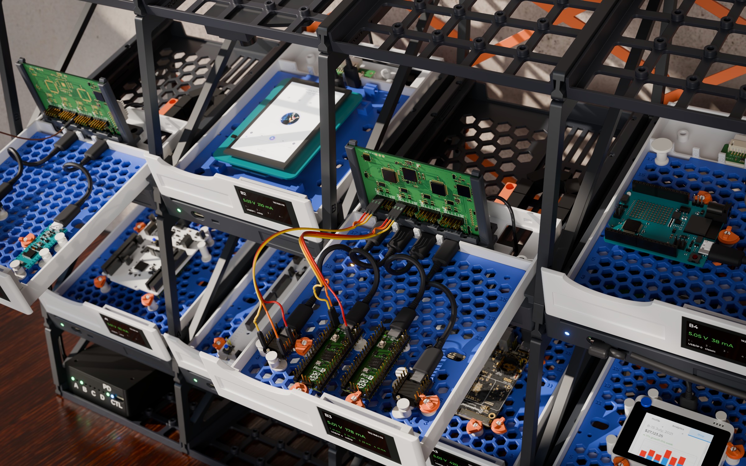
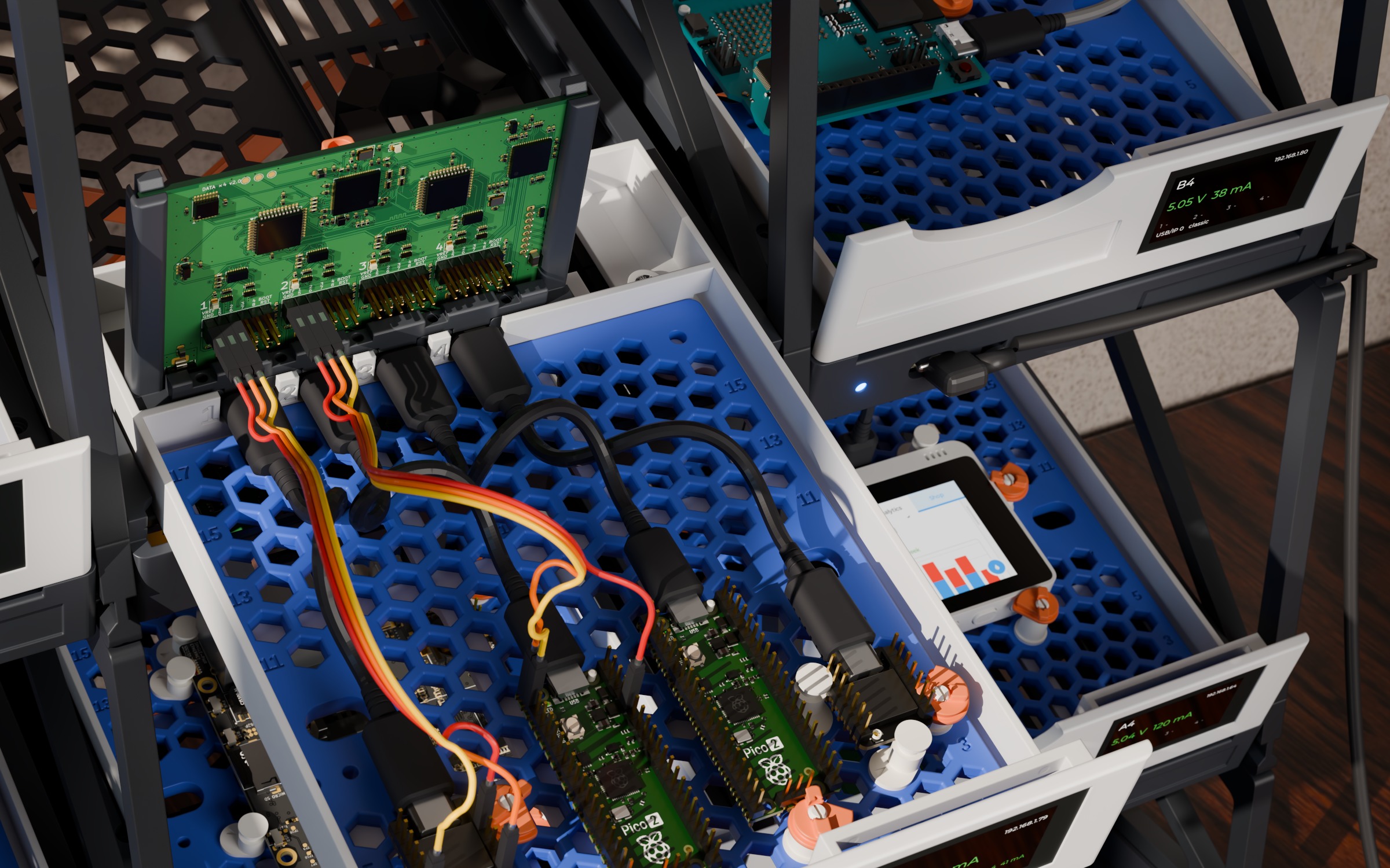
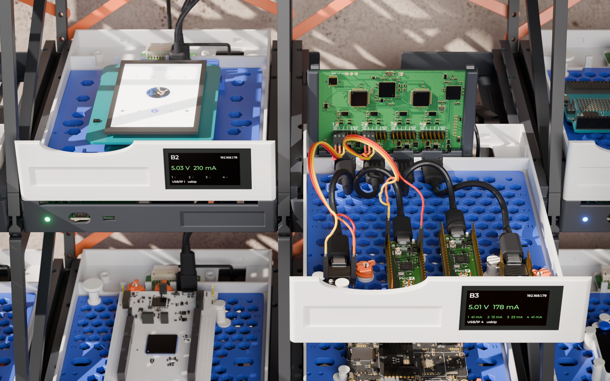
Bay B3 pulled out, still connected: a DATA ×4 at the back serves two XIAOs and two Pico 2s
The DATA ×4 up close: a USB-C lead per board, Dupont jumpers wiring a UART between two of them (real models)
Row B: the GIGA's LVGL screen in B2, between two DATA ×4 bays
Bay node — ESP32-S3 (8 MB PSRAM), 2 USB muxes, TPS26600 eFuse, INA226, CAN, 60 V buck
config/rack.yaml          single source of truth (rows, bays, tilt, dimensions, population)
mechanical/               OpenSCAD: lib/, parts/, boards/boards.yaml, generated/ (from the config)
electronics/
  tools/                  schematic-as-code (eda.py), PCB builder (pcbgen.py), catalogue, LCSC resolver
  bay-node/               design.py + generated KiCad project, fab/, docs/
  power-hub/              design.py + generated KiCad project, fab/, docs/
  data-port-x6/           the drawer's DATA ×6, six USB-C, power only (the default): design.py + KiCad, fab/, docs/
  data-port-x4/           the DATA ×4 v2, four USB-C and the logic, for bays with wires: design.py + KiCad, fab/, docs/
  data-port/              the single-port board, retired from the rack, kept for the standalone Solo box
  camera-pod/             the camera pod's board (lead, camera header, 3.3 V, LEDs): design.py + KiCad, fab/, docs/
  lib/                    custom symbol(s), cached JLC basic passives
site/                     GitHub Pages: three.js viewer + BOM page (assets generated)
bom/                      full rack BOM (CSV + summary)
render/                   Blender scene + photoreal renders
tools/                    build.py (config/STL/web), kicad.sh, bom.py, jlc_mcp.py, notice/ (FreeCAD line art)
docs/                     design documentation
Building
Prerequisites: Python ≥ 3.10 with pyyaml numpy trimesh (pip install -r tools/requirements.txt),
Docker (for KiCad 10, Freerouting and — if not installed locally — OpenSCAD).
bash
python tools/build.py all # config → STLs → web viewer assets
tools/kicad.sh bay-node --route --fab # schematic, PCB, autoroute, Gerbers/BOM/CPL, renders
tools/kicad.sh power-hub --route --fab
tools/kicad.sh data-port-x6 --fab # fab outputs of the routed board, no re-route
tools/kicad.sh data-port-x4 --fab
tools/kicad.sh camera-pod --route --fab
python tools/bom.py # full rack BOM
python -m http.server -d site 8000# open http://localhost:8000
Generated outputs (STLs, Gerbers, renders, PDFs, GLBs, the BOM) are committed with the change that alters
them, never for a date: python tools/keep_unchanged.py puts back every regenerated file whose content didn't
change (tools/kicad.sh … --fab runs it on its board).
For screenshots the viewer takes URL parameters: ?bay=B4&openbay=1&view=dut&hideui
pulls bay B4's drawer out and frames its DUT cable (DATA port to board), with no UI.
?bay=B2&view=camera&camlight=1&preview=B2 looks into a camera bay with its LEDs on and opens what
its camera sees (an Arducam Mega with a ~120° lens: fisheye, noise, auto-exposure and JPEG, at 5 fps).
The viewer lights the rack like the photos: a real room (Poly Haven's "Small Empty Room 1", CC0, cut to
512 × 256 in site/assets/env/), AgX with Blender's "Medium High Contrast" look, PETG with its layer lines.
Its High quality box (on by default on a desktop GPU, off on phones and small GPUs, and dropped by itself
under 25 fps) adds ambient occlusion (GTAO), a glow on the status LEDs and the camera lights, 4× MSAA through
the post-processing and 4096² sun shadows; ?quality=high or ?quality=low forces one for screenshots.
Photoreal renders (Blender + Cycles) start from render/assembly.glb, baked
from the same scene as the viewer by python tools/assembly_glb.py --hq (--hq:
full-resolution part meshes instead of the viewer's lighter ones). Either
render headless in Docker (tools/render.sh hero) or drive a Blender you
already have open — GPU and all — through the Blender MCP add-on's socket:
The photo shots (docs/img/photo-*.jpg) use their own scene: a small office
lit through a window, PETG with 0.2 mm layer lines and
rounded edges, scanned oak and plaster (CC0 textures from Poly Haven), a laptop
showing a Zephyr shell, wired to bay B4 by a USB-C cable that hangs as a real
one would (a catenary), depth of field, bloom and a vignette, rendered at 2× and averaged down:
bash
python tools/fetch_render_assets.py # CC0 textures + vendor board models → render/assets/
python tools/board_models.py # normalise the board models (docs/boards-3d.md)
python render/screen_terminal.py # the laptop's screen → render/assets/
node tools/lvgl_frame.mjs music 480800# B2's GIGA display: one frame of the viewer's LVGL demo# (the drawer fronts' status screens: assembly_glb.py draws them)
python tools/assembly_glb.py --hq --with-pc-cable --open-bays B3 --out render/assembly-photo.glb
python tools/blender_live.py exec render/live_photo.py build
python tools/blender_live.py exec render/live_photo.py shot desk # desk, drawer, detail → docs/img/photo-*.jpg
Change the rack in config/rack.yaml (tilt, rows, columns, panel thickness,
which bays get cameras, which board sits where) and rebuild.
Status
v0.2 — the printed panel frame replaces the aluminium frame, not yet
built. Mechanics are printable and parametric, the power box included;
still to design: double-width bays (see mechanical.md).
Each drawer front carries the node's 1.9" touch display, waiting on the
module to check its fit before a test print. Five PCBs (bay node, power hub,
DATA port, DATA ×4 v2, camera pod) pass ERC and DRC, are routed and smoothed,
and went through a schematic review
(schematic-review-2026-10-25.md) and a
datasheet audit; none is fabricated yet (see
electronics.md). The node firmware:
firmware.md.
Board outlines marked verified: false in boards.yaml are approximate.
License
Hardware (mechanical and electronics design files): CERN-OHL-P-2.0.
Software (tools, viewer, firmware): Apache-2.0. See LICENSE.
3D-printed, tilted test shelf for 16 dev boards: sliding drawers, per-bay ESP32-S3 running Zephyr (USB/IP, power switching, metering), KiCad PCBs, OpenSCAD parts, BOM and an interactive 3D viewer
3D-printed, tilted test shelf for 16 dev boards: sliding drawers, per-bay ESP32-S3 running Zephyr (USB/IP, power switching, metering), KiCad PCBs, OpenSCAD parts, BOM and an interactive 3D viewer
3D-printed, tilted test shelf for 16 dev boards: sliding drawers, per-bay ESP32-S3 running Zephyr (USB/IP, power switching, metering), KiCad PCBs, OpenSCAD parts, BOM and an interactive 3D viewer
3D-printed, tilted test shelf for 16 dev boards: sliding drawers, per-bay ESP32-S3 running Zephyr (USB/IP, power switching, metering), KiCad PCBs, OpenSCAD parts, BOM and an interactive 3D viewer
3D-printed, tilted test shelf for 16 dev boards: sliding drawers, per-bay ESP32-S3 running Zephyr (USB/IP, power switching, metering), KiCad PCBs, OpenSCAD parts, BOM and an interactive 3D viewer
It measures 100 × 70 mm and has 4 copper layers, 1.6 mm thick.
What parts does the Data port x4 use?
290 parts, built around the RP2350B, INA226AIDGSR, USB2517I-JZX and H5VU25UC. The full list of its parts is on this page, with links to each part's symbol and footprint where PCBKit's library has them.
Where can I download the Data port x4 KiCad files?
From the kartben/hw-testing-rack repository on GitHub, at the commit this page was made from: the board is electronics/data-port-x4/data-port-x4.kicad_pcb and its schematic electronics/bay-node/bay-node.kicad_sch. PCBKit opens the board in the browser, with nothing to install.
Can I use the Data port x4 design in my own project?
Its repository states no licence, so its author keeps all rights: ask kartben before reusing the design.