

2 layers112.6 × 85.4 mm

 kanta/GARAGE-SAILING1
KiCad 6.0 project files for the top and the bottom panel.
FM radio esp32 hardware is an open-source printed circuit board by kanta, from the kanta/GARAGE-SAILING repository on GitHub, published under the MIT licence. It is a 2-layer board of 85 × 117 mm with 47 parts on 57 nets, routed with 341 tracks and 59 vias.
It is built around the ESP32-WROOM-32D and RDA5807M. Its parts include 7 capacitors, 7 resistors, 4 connectors, 3 diodes and 3 switches. It belongs with the radio and wireless boards and the ESP32 boards of this library.
KiCad 6.0 project files for the top and the bottom panel.
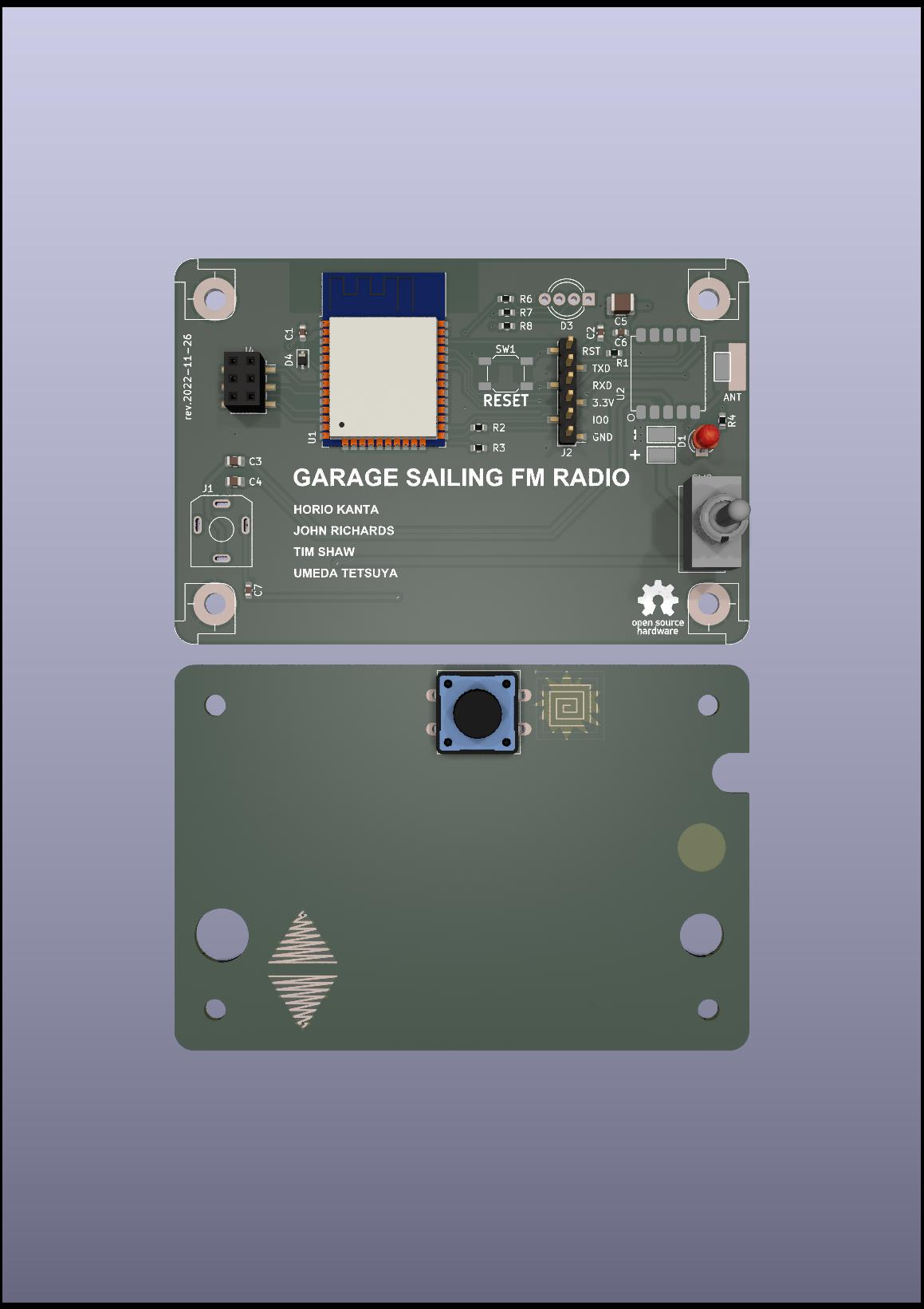
BOM list: https://docs.google.com/spreadsheets/d/1gx5q1M0V2GI4ifzEtNZcrifsvwdLu0RDMLZBMcAdJLQ/edit?usp=sharing
| Qty | Value | Footprint | References |
|---|---|---|---|
| 4 | MountingHole | MountingHole:MountingHole_3.2mm_M3 | H6, H7, H8, H9 |
| 4 | MountingHole_Pad | MountingHole:MountingHole_3.2mm_M3_Pad | H2, H3, H4, H5 |
| 3 | 10k | Resistor_SMD:R_0603_1608Metric | R1, R2, R3 |
| 2 | 0.1uF | Capacitor_SMD:C_0603_1608Metric | C1, C6 |
| 2 | 10uF | Capacitor_SMD:C_0805_2012Metric | C3, C4 |
| 2 | 1k | Resistor_SMD:R_0603_1608Metric | R4, R8 |
| 2 | 330 | Resistor_SMD:R_0603_1608Metric | R6, R7 |
| 2 | TestPoint | TestPoint:TestPoint_Keystone_5019_Minature | TP1, TP2 |
| 1 | 1nF | Capacitor_SMD:C_0603_1608Metric | C7 |
| 1 | 1u | Capacitor_SMD:C_0603_1608Metric | C2 |
| 1 | 47uF | Capacitor_SMD:C_1210_3225Metric | C5 |
| 1 | AudioJack2_Ground_SwitchT | FM_radio_esp32:Jack_3.5mm_RS_913-1055 | J1 |
| 1 | Conn_01x06 | Connector_PinHeader_2.54mm:PinHeader_1x06_P2.54mm_Vertical_SMD_Pin1Left | J2 |
| 1 | Conn_02x03_Odd_Even | Connector_PinHeader_2.54mm:PinHeader_2x03_P2.54mm_Vertical_SMD | J3 |
| 1 | Conn_02x03_Odd_Even | Connector_PinSocket_2.54mm:PinSocket_2x03_P2.54mm_Vertical_SMD | J4 |
| 1 | D_Zener | Diode_SMD:D_SOD-323 | D4 |
| 1 | ESP32-WROOM-32D | RF_Module:ESP32-WROOM-32 | U1 |
| 1 | LED | FM_radio_esp32:LED_D3.0mm | D1 |
| 1 | LED_RGBK | LED_THT:LED_D5.0mm-4_RGB_Wide_Pins | D3 |
| 1 | LOGO | FM_radio_esp32:GS_text_logo_credit | G*** |
| 1 | LOGO | FM_radio_esp32:electronics_fig_5_s2 | G*** |
| 1 | LOGO | FM_radio_esp32:umeda_ninja | G*** |
| 1 | MountingHole | MountingHole:MountingHole_6.5mm | H11 |
| 1 | MountingHole | FM_radio_esp32:Hole_8mm | H10 |
| 1 | MountingHole_Pad | TestPoint:TestPoint_Keystone_5019_Minature | H1 |
| 1 | RDA5807 | FM_radio_esp32:RDA5807H | U2 |
| 1 | SW_Push | Button_Switch_SMD:SW_SPST_SKQG_WithoutStem | SW1 |
| 1 | SW_SPDT | FM_radio_esp32:Toggle_Sw_1MS1-T1-B1-M1-Q-N | SW2 |
| 1 | SW_SPST | Button_Switch_THT:SW_PUSH-12mm | SW3 |
The 42 most common of 47 parts.


Longing-Ingernot/FMTransceiver
This is an FM radio transmitter and receiver, all in one, built around an ESP32-S3, a KT0803L

Benjamin324/Alarm-Clock-Radio-ECE-299-
Micropython and Html establishing alarm clock and radio functionality on a rasperry pi pico w.

ItzzInfinity/FM-Radio-Using-ESP-12E-and-RDA5807M
An FM radio receiver built using an ESP12E, interfaced with the RDA5807M module. Powered by a Li-Ion battery with a TP4056 charging module, amplified by a PAM8403, and output through a 10-watt speaker.

mit41301/RDA5807M-arduino-nano-clone-FM-radio
RDA5807M (+ arduino nano clone) FM radio with NEC IR remote control

tend876/Card-Radio-1
The 1986 Casio RD-10 was an 86 × 54 × 2.2 mm card with a Philips TDA7020T, a CR2016 cell and a proprietary flat earphone plug. The earphone lead was also the antenna and the power switch.
It measures 85 × 117 mm and has 2 copper layers, 1.6 mm thick.
47 parts, built around the ESP32-WROOM-32D and RDA5807M. The full list of its parts is on this page, with links to each part's symbol and footprint where PCBKit's library has them.
From the kanta/GARAGE-SAILING repository on GitHub, at the commit this page was made from: the board is GarageSailing-FM-radio/FM_radio_esp32_hardware/FM_radio_esp32_hardware.kicad_pcb and its schematic GarageSailing-FM-radio/FM_radio_esp32_hardware/FM_radio_esp32_hardware.kicad_sch. PCBKit opens the board in the browser, with nothing to install.
Its repository publishes it under the MIT licence: you may reuse it on that licence's terms (keep the author's notice, and for a copyleft licence share your changes alike).