
2 layers72.8 × 32 mm

An FM radio receiver built using an ESP12E, interfaced with the RDA5807M module. Powered by a Li-Ion battery with a TP4056 charging module, amplified by a PAM8403, and output through a 10-watt speaker. Features station switching via a button.
05 a radio is an open-source printed circuit board by ItzzInfinity, from the ItzzInfinity/FM-Radio-Using-ESP-12E-and-RDA5807M repository on GitHub, published under the MIT licence. It is a 2-layer board of 47.4 × 28.3 mm with 15 parts on 35 nets, routed with 84 tracks and 16 vias.
It is built around the RDA5807M, ESP-12E and AMS1117-3.3. Its parts include 4 capacitors and 1 IC. It belongs with the radio and wireless and power boards and the ESP32, ESP8266 and RISC-V boards of this library.





A small FM receiver built around the RDA5807M, driven over I2C by either an ESP32-C3 SuperMini or an ESP-12E — the carrier board has a footprint for both and the firmware picks its pin map from whichever core you compile for.
Audio leaves the board on a 2-pin header to a PAM8403 amplifier and a speaker;
a telescopic antenna solders to a plated mounting hole. Beyond the original
button-cycles-presets behaviour, the current firmware brings up Wi-Fi and serves
a web UI at http://radio.local for presets, volume, seek and manual tuning,
supports OTA reflashing, and optionally drives an SSD1306/SH1106 OLED.
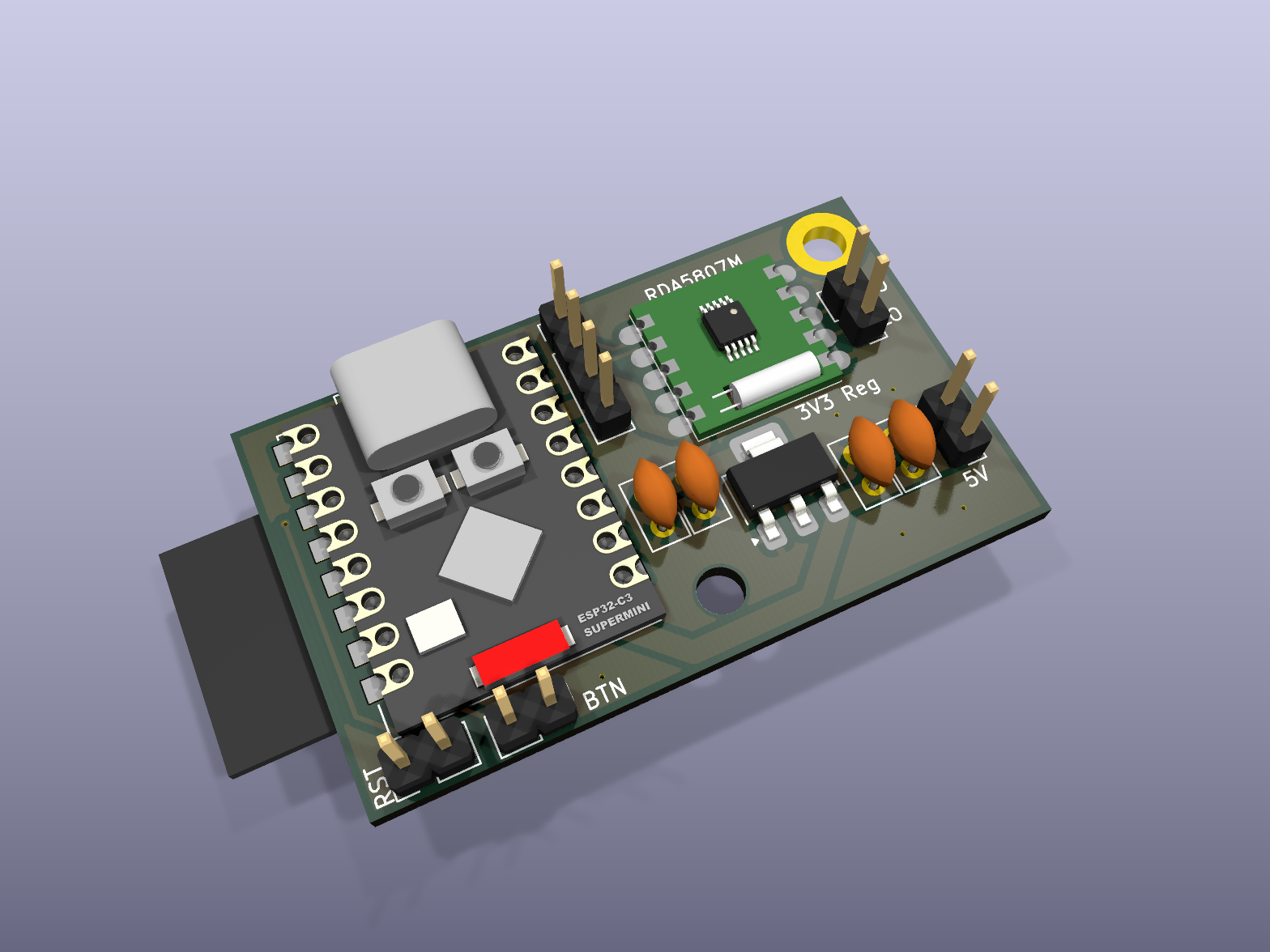
The board is a 2-layer 47.4 × 28.2 mm carrier. Reference designators differ between the schematic and the PCB silkscreen — both are listed below.
| Sch | Silkscreen | Part | Notes |
|---|---|---|---|
| U1 | ESP32C3 SuperMini | ESP32-C3 SuperMini | Top side, through-hole module |
| U2 | ESP12E | ESP-12E | Bottom side — the alternate MCU, see below |
| U3 | U3 | RDA5807M module (RRD-102/120 style) | I2C 0x10 (sequential) / 0x11 (indexed) |
| U4 | 3V3 Reg | AMS1117-3.3, SOT-223 | Only needed for the ESP-12E build |
| C1, C2 | C1, C2 | Ceramic disc, 5 mm THT | AMS1117 input side |
| C3, C4 | C3, C4 | Ceramic disc, 5 mm THT | AMS1117 output side |
| J2 | GND | 1×4 header | I2C breakout: SDA, SCL, 3V3, GND — for the OLED |
| J3 | 5V | 1×2 header | 5 V supply in |
| J4 | LO | 1×2 header | Audio out: LOUT, ROUT → PAM8403 |
| SW1 | RST | 1×2 header | Reset, broken out for an external button |
| SW2 | BTN | 1×2 header | Preset button, broken out for an external button |
| H1 | H1 | M3 mounting hole | |
| H2 | H2 | M3 plated mounting hole | Carries the ANT net — solder the antenna here |
Notes on the BOM:
C with 5 mm disc footprints. Fill them in before ordering; the
AMS1117 datasheet wants at least 10 µF on the output for stability, which a
disc ceramic will not give you.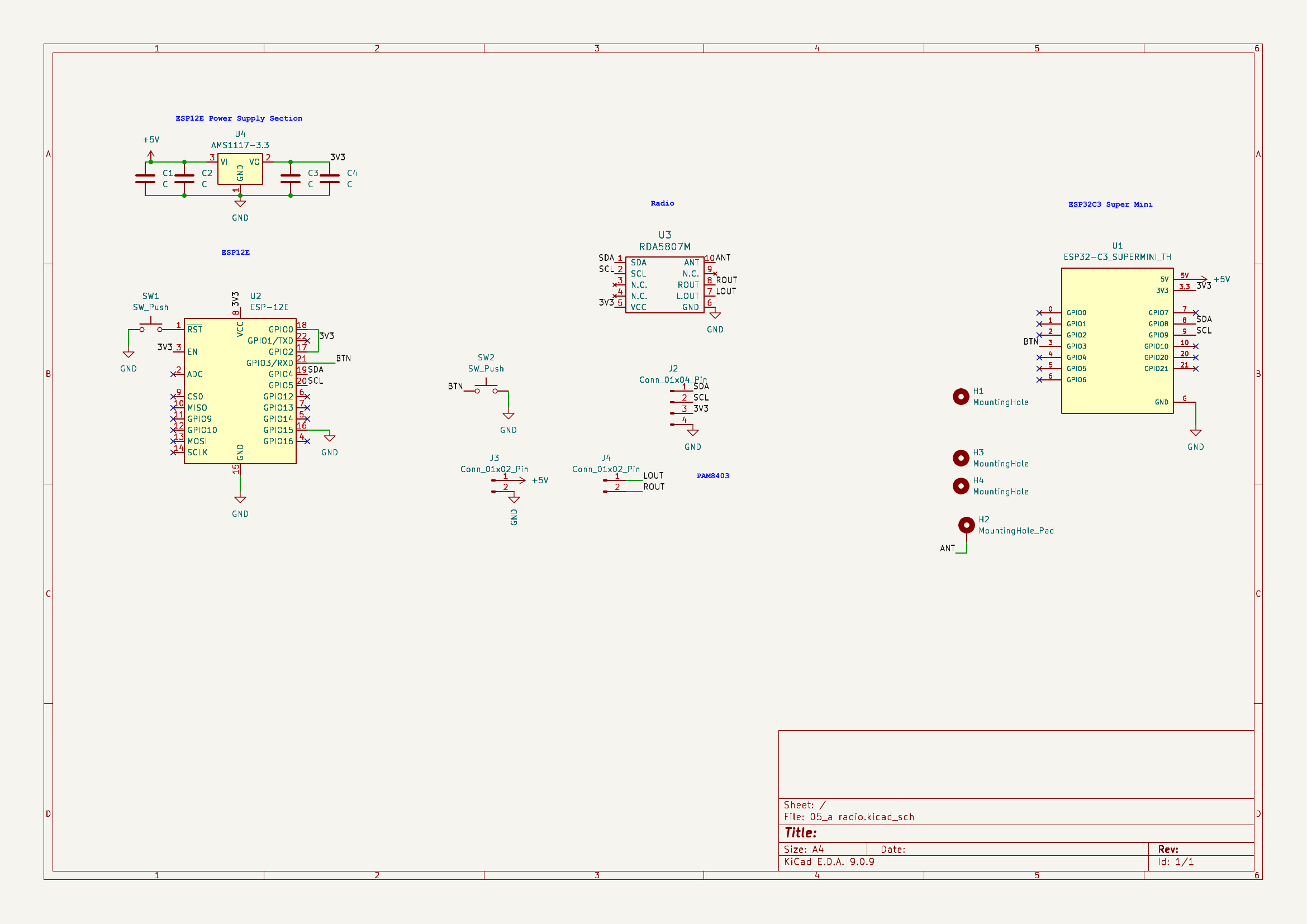
Click for the full-resolution PDF.
| Top | Bottom |
|---|---|
| 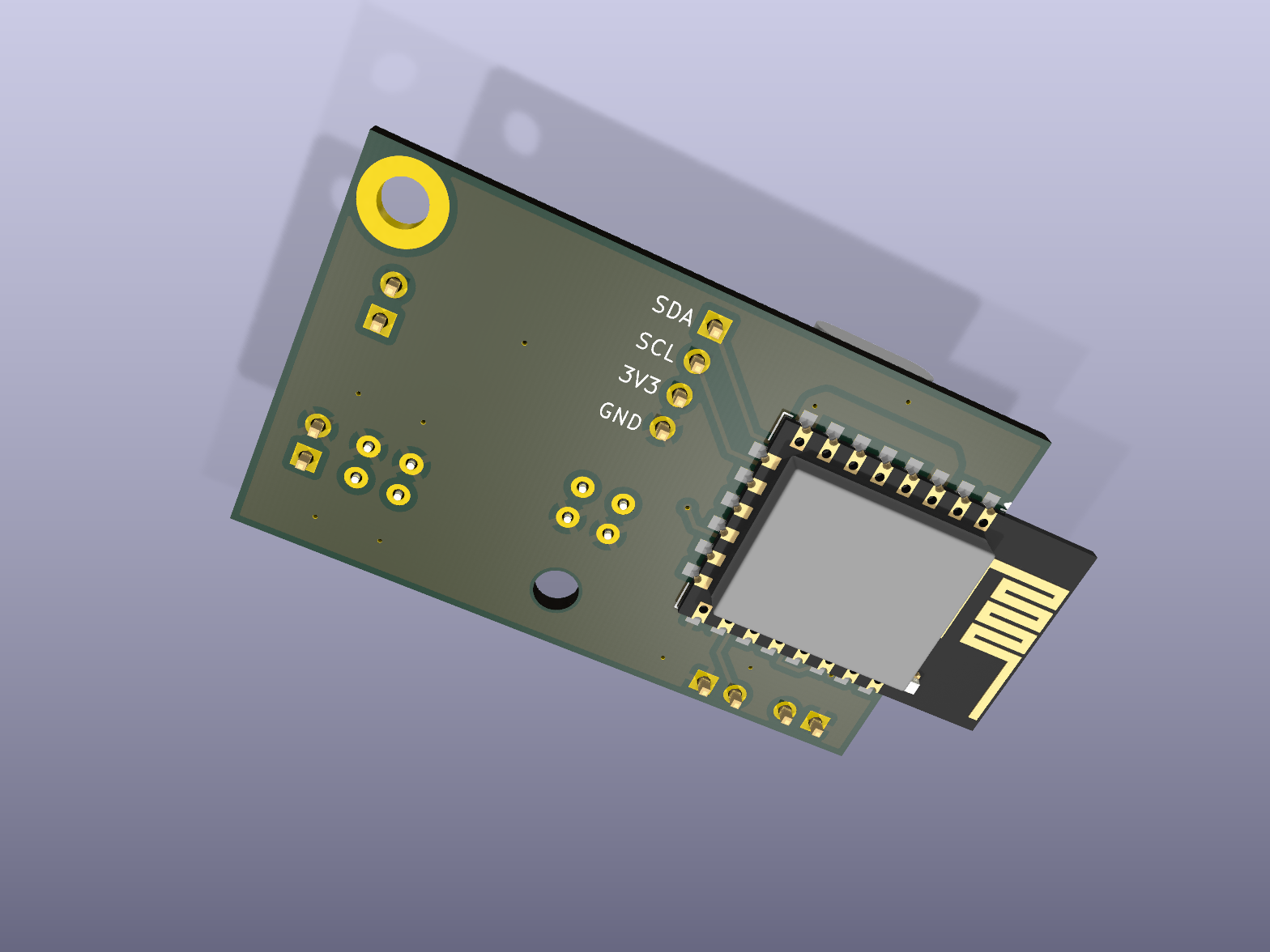 |
The KiCad 9 project is in hardware/. Both custom 3D models
(ESP32-C3 supermini v5.step, RDA5807m-RRD-120.step) are committed and
referenced through ${KIPRJMOD}, so a fresh clone renders identically:
mkdir -p docs/images

kicad-cli sch export pdf -o docs/images/schematic.pdf "hardware/05_a radio.kicad_sch"
pdftoppm -r 200 -png -singlefile docs/images/schematic.pdf docs/images/schematic

kicad-cli pcb render --side top --quality high --perspective \
  --rotate '-25,0,25' --zoom 0.7 --width 1600 --height 1200 --floor \
  --background opaque -o docs/images/pcb-top.png "hardware/05_a radio.kicad_pcb"

kicad-cli pcb render --side bottom --quality high --perspective \
  --rotate '25,0,25' --zoom 0.52 --width 1600 --height 1200 --floor \
  --background opaque -o docs/images/pcb-bottom.png "hardware/05_a radio.kicad_pcb"
Gerbers are not committed — the exports under hardware/Drill/ predated the
current layout, so they are gitignored. Regenerate with
kicad-cli pcb export gerbers before ordering.
| Signal | ESP32-C3 (U1) | ESP-12E (U2) | Goes to |
|---|---|---|---|
| SDA | GPIO8 | GPIO4 (D2) | RDA5807M + J2 (OLED) |
| SCL | GPIO9 | GPIO5 (D1) | RDA5807M + J2 (OLED) |
| Button | GPIO3 | GPIO3 (RXD) | BTN header → GND |
| Reset | — | RST | RST header → GND |
These are the same values the firmware compiles in; the pin map lives in
section 2 of the sketch, keyed off ESP8266 / ARDUINO_ARCH_ESP32.
Populate one MCU, not both. The ESP-12E sits on the bottom copper and the SuperMini on the top, so nothing physically stops you fitting both — but they share the I2C bus and the 3V3 rail. Pick one.
Two regulators land on the same 3V3 net. U1's 3.3 pin and the AMS1117's
output are the same node. With the SuperMini fitted, its onboard LDO already
powers the rail from the 5 V input, so leave 3V3 Reg (U4) and C3/C4
unpopulated. The AMS1117 is only there for the ESP-12E build.
GPIO8 and GPIO9 are ESP32-C3 strapping pins. They are also the I2C bus here. The chip samples both at reset — GPIO9 low selects download mode, and GPIO8 must not be low — so the bus pull-ups have to be strong enough that nothing on the bus drags either line down during boot. If the board only enumerates as a serial port and never runs, this is the first thing to check.
On the ESP-12E, pinMode() on GPIO3 detaches it from UART0 RX: serial output
keeps working, serial input does not. That is inherited from the original
board and left as-is.
No radio library. The RDA5807M driver is ~180 lines in section 4 of the sketch. The chip is simple enough — 16-bit big-endian registers, two I2C addresses (0x10 auto-incrementing, 0x11 indexed) — that a dependency buys nothing and costs portability across the two cores.
One sketch, two targets, no manual switch. Everything board-specific is
behind #if defined(ESP8266) / #elif defined(ARDUINO_ARCH_ESP32): pin map,
network headers, the web server type, and the persistence backend (EEPROM on
the ESP8266, Preferences on the ESP32). Selecting the board in the IDE is the
only choice you make.
The OLED type is a runtime setting, not a compile-time one. SSD1306 and
SH1106 are indistinguishable over I2C, so the firmware auto-detects that an
OLED is present and lets you switch the controller from the web page. Getting
the wrong module in a batch costs a click instead of a reflash. OLED_ENABLED 0
compiles the whole display path out.
Audio survives an OTA update. The RDA5807M only needs the MCU to change
station — it keeps playing on its own while flash is being rewritten. Both OTA
paths (the Arduino IDE network port and the browser upload at /update) are
guarded by OTA_PASSWORD, because otherwise anyone on the LAN can replace the
firmware. A failed transfer rolls back to the old image; only a successfully
written but broken sketch means opening the box.
Credentials are gitignored. This repo is public, so Wi-Fi and OTA passwords
live in secrets.h, which is not tracked. secrets.h.example is the template.
The web page is served from flash at / and drives these endpoints:
| Endpoint | Purpose |
|---|---|
GET /api/status | Current frequency, volume, stereo/RSSI, preset list |
GET /api/preset | Select a preset slot |
GET /api/tune | Tune to a frequency |
GET /api/volume | Set volume 0–15 |
GET /api/seek | Hardware seek up/down |
GET /api/preset/set | Rewrite a preset slot (persisted) |
GET /api/oled | Switch controller: ssd1306 / sh1106 / none |
GET/POST /update | Browser firmware upload |
cp Src/test_I2C_Radio/secrets.h.example Src/test_I2C_Radio/secrets.h
$EDITOR Src/test_I2C_Radio/secrets.h

# ESP32-C3 SuperMini
arduino-cli compile --fqbn esp32:esp32:esp32c3 Src/test_I2C_Radio

# ESP-12E
arduino-cli compile --fqbn esp8266:esp8266:nodemcuv2 Src/test_I2C_Radio
Requires the Adafruit SSD1306, Adafruit SH110X, Adafruit GFX and
Adafruit BusIO libraries unless you set OLED_ENABLED 0.
Verified with arduino-cli 1.5.1, esp32 core 3.3.8, esp8266 core 3.1.2:
| Target | Flash | RAM |
|---|---|---|
| ESP32-C3 | 1,130,767 / 1,310,720 B (86%) | 44,252 / 327,680 B (13%) |
| ESP-12E | 340,684 / 1,048,576 B (32%) | 31,864 / 80,192 B (39%) |
Two figures worth watching: the ESP32-C3 build is at 86% of the default 1.3 MB app partition, and the ESP-12E build sits at 93% of IRAM (61,551 / 65,536 B). Neither has much headroom left for new features.
secrets.h.example → secrets.h and fill in your Wi-Fi credentials
and an OTA password.LO header to a PAM8403 input and feed 5 V into the 5V header.
Take the amplifier's ground from that same header — LO carries only LOUT
and ROUT, no ground of its own.http://radio.local. If mDNS does not resolve, check the serial
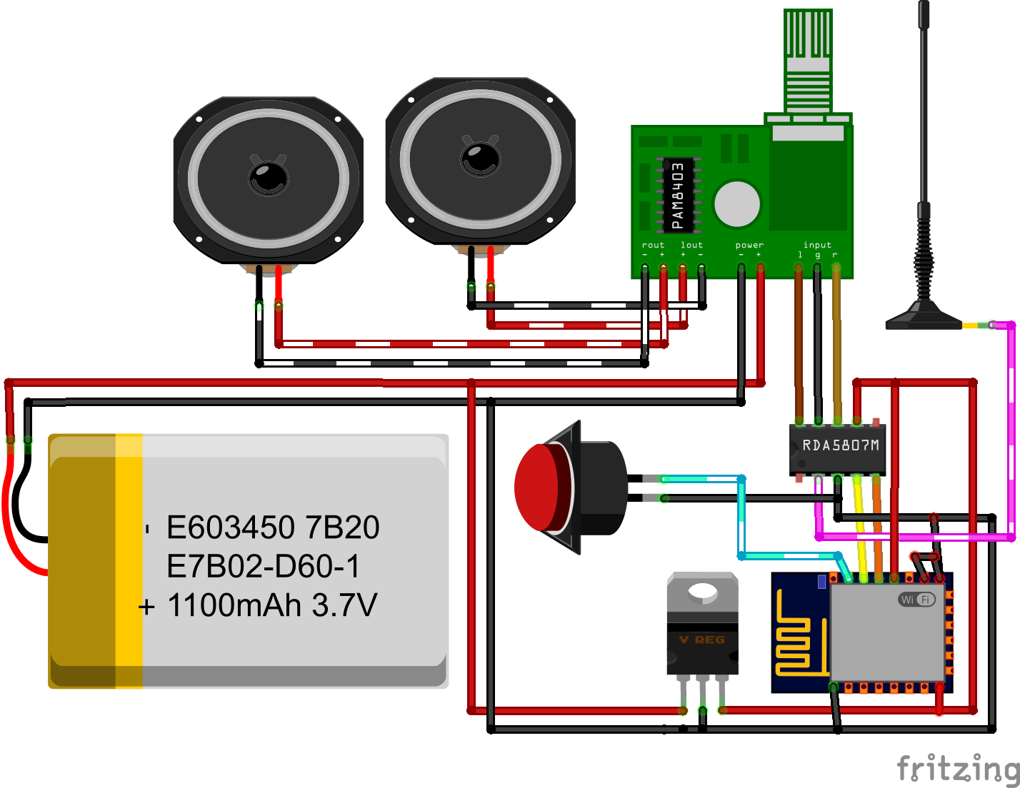
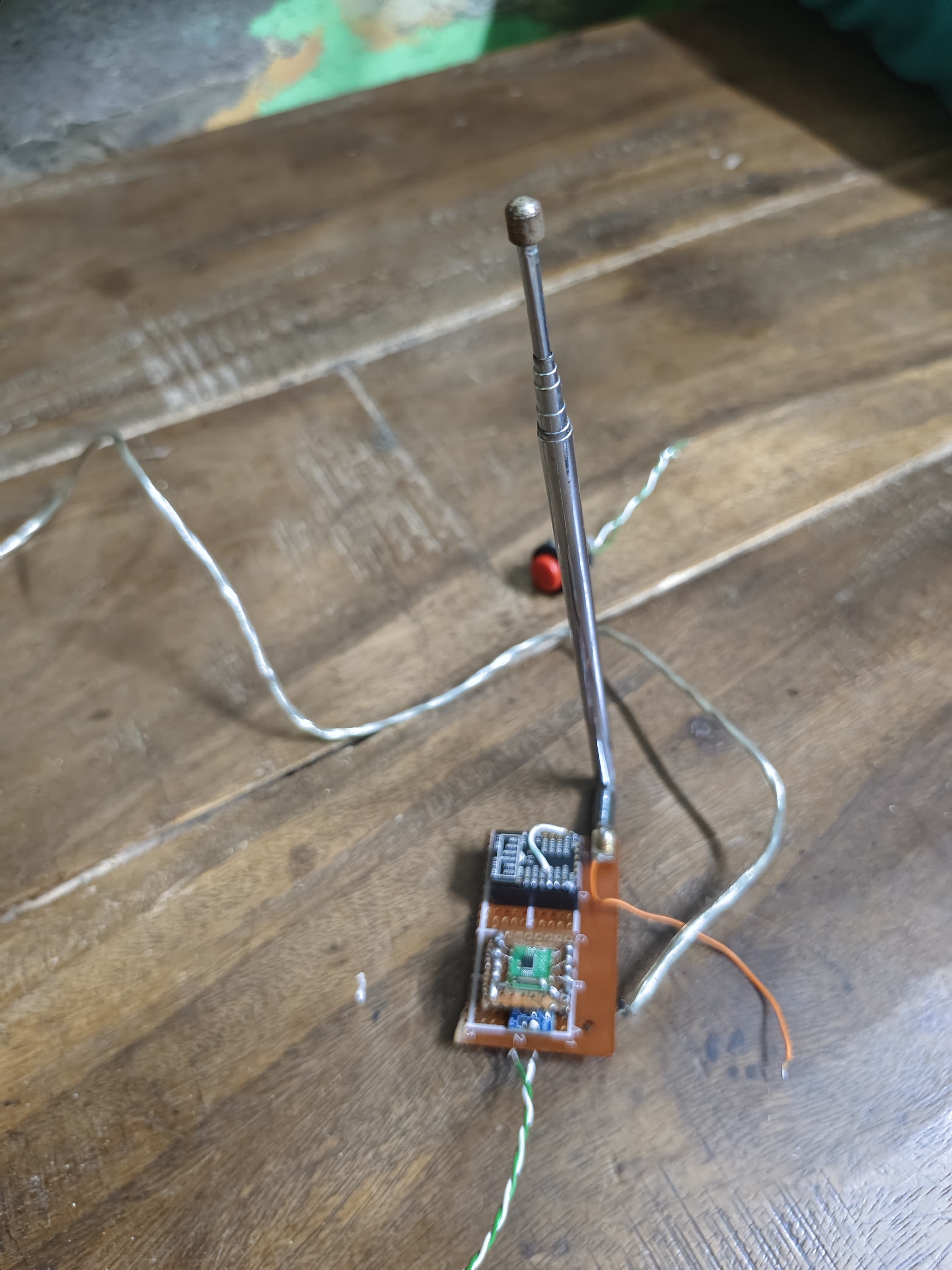
log for the DHCP address.BTN header cycles presets.The first version of this project was a hand-soldered perfboard build on an ESP-12E with a fixed volume and 10 hard-coded stations — no Wi-Fi, no display, one button. The carrier board above replaces it.
| Breadboard wiring | Perfboard build |
|---|---|
 |  |
MIT — see LICENSE.
| Qty | Value | Footprint | References |
|---|---|---|---|
| 4 | C | Capacitor_THT:C_Disc_D5.0mm_W2.5mm_P2.50mm | C1, C2, C3, C4 |
| 2 | Conn_01x02_Pin | Connector_PinHeader_2.54mm:PinHeader_1x02_P2.54mm_Vertical | 5V, LO |
| 2 | SW_Push | Connector_PinHeader_2.54mm:PinHeader_1x02_P2.54mm_Vertical | BTN, RST |
| 1 | AMS1117-3.3 | Package_TO_SOT_SMD:SOT-223-3_TabPin2 | 3V3 Reg |
| 1 | Conn_01x04_Pin | Connector_PinHeader_2.54mm:PinHeader_1x04_P2.54mm_Vertical | GND |
| 1 | ESP-12E | RF_Module:ESP-12E | ESP12E |
| 1 | ESP32-C3_SUPERMINI_TH | ESP32-C3_SUPERMINI:MODULE_ESP32-C3_SUPERMINI | ESP32C3 SuperMini |
| 1 | MountingHole | MountingHole:MountingHole_3.2mm_M3 | H1 |
| 1 | MountingHole_Pad | MountingHole:MountingHole_3.2mm_M3_DIN965_Pad_TopBottom | H2 |
| 1 | RDA5807M | PAM8403_module:RDA5807M_SMD | U3 |

Longing-Ingernot/FMTransceiver
This is an FM radio transmitter and receiver, all in one, built around an ESP32-S3, a KT0803L


kanta/GARAGE-SAILING
KiCad 6.0 project files for the top and the bottom panel.

Benjamin324/Alarm-Clock-Radio-ECE-299-
Micropython and Html establishing alarm clock and radio functionality on a rasperry pi pico w.

mit41301/RDA5807M-arduino-nano-clone-FM-radio
RDA5807M (+ arduino nano clone) FM radio with NEC IR remote control

tend876/Card-Radio-1
The 1986 Casio RD-10 was an 86 × 54 × 2.2 mm card with a Philips TDA7020T, a CR2016 cell and a proprietary flat earphone plug. The earphone lead was also the antenna and the power switch.
It measures 47.4 × 28.3 mm and has 2 copper layers, 1.6 mm thick.
15 parts, built around the RDA5807M, ESP-12E and AMS1117-3.3. The full list of its parts is on this page, with links to each part's symbol and footprint where PCBKit's library has them.
From the ItzzInfinity/FM-Radio-Using-ESP-12E-and-RDA5807M repository on GitHub, at the commit this page was made from: the board is hardware/05_a radio.kicad_pcb and its schematic hardware/05_a radio.kicad_sch. PCBKit opens the board in the browser, with nothing to install.
Its repository publishes it under the MIT licence: you may reuse it on that licence's terms (keep the author's notice, and for a copyleft licence share your changes alike).