2 layers94 × 63 mm
New buck
wurflrll/Lithium-Battery_Charger
The goals is a modular design for charging a lithium ion battery. The board has two parts, the actual charging circuitry and the communication peripherals.
116 parts

 Kampi/SensorHub1
Solar-powered, low energy environment sensor node with WiFi interface.
SensorHub is an open-source printed circuit board by Kampi, from the Kampi/SensorHub repository on GitHub, published under the GPL-3.0 licence. It is a 2-layer board of 72 × 50 mm with 42 parts on 39 nets, routed with 176 tracks and 38 vias.
It is built around the VEML6070-SB, BME680 and MCP9808-E/MS, with the LT3652EMSE#PBF and ZLLS500TA among its other parts. Its parts include 16 resistors, 8 capacitors, 5 ICs, 2 diodes and 2 crystals. It belongs with the home automation and IoT and radio and wireless boards of this library.


Solar-powered, low energy environment sensor node with WiFi interface. The device will measure the following parameter:
The whole device is designed for low power operation and for a solar panel as current source. A backup battery will be used to buffer the sun-free time during the night or on cloudy days. This battery will be charged by an integrated solar-charging circuit.
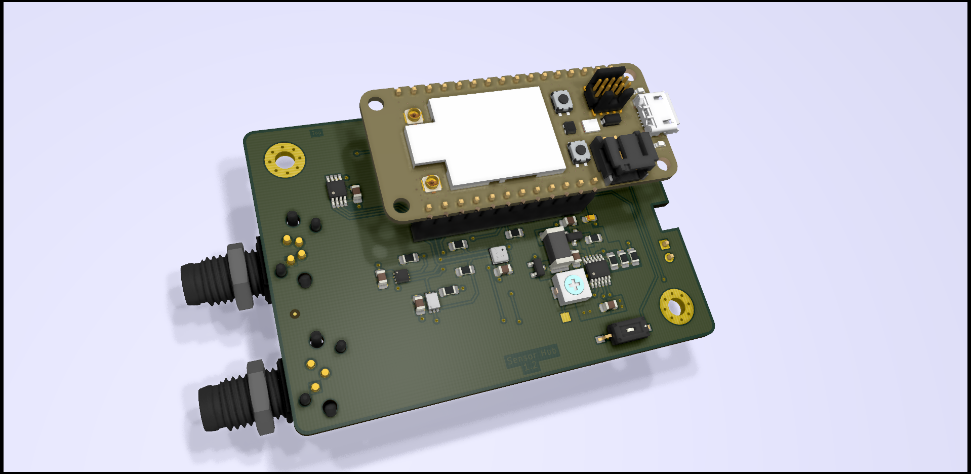
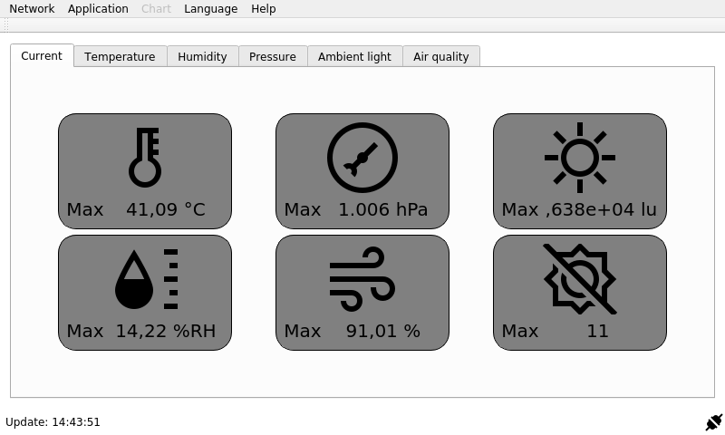
The integrated WiFi is used to transmit the data as an MQTT message to a broker (i. e. a Raspberry Pi). The included Qt application for the Raspberry Pi can be used to visualize and record the received data.
Please visit the project site or write me an e-mail when you need additional informations or if you have any questions.
$ particle usb start-listening
Done.

$ particle serial wifi
? Should I scan for nearby Wi-Fi networks? (Y/n) y
? Should I scan for nearby Wi-Fi networks? Yes
? SSID ...
? SSID ...
? Security Type (Use arrow keys)
? Security Type ...
? Cipher Type (Use arrow keys)
? Cipher Type ...
? Wi-Fi Password ...
? Wi-Fi Password ...
Done! Your device should now restart.software/SensorHub by using Visual Studio Code and the Particle Workbench.SensorHub and flash the firmware from software/release by using the Particle CLI.MODE button of the microcontroller module to enter the setup mode.SensorHub. When the connection is successful the RGB LED of the SensorHub starts to blink green until you close the connection or a IP address of the MQTT broker was transmitted successfully.The SensorHub use the RGB led of the microcontroller module to display his current state. Each state is encoded in a blink pattern which begins with a 3 seconds group color.
| RGB color | Group |
|---|---|
| Blue | Sensors |
| Green | Network |
| Red | Device |
The group color is followed by the error code which is encoded with a white flashing of the RGB LED. Each flash has a duration of 1 second.
| Blink code | Sensors | Network | Device |
|---|---|---|---|
| 1x | Temperature sensor failure. | No valid WiFi credentials found. Please use the Particle CLI to setup your WiFi credentials. | - |
| 2x | Light sensor failure. | No valid IP address found. | - |
| 3x | Environment sensor failure. | Connection error. | - |
| 4x | UV sensor failure. | Network timeout. | - |
| 5x | Communication error. | - | - |
The current device error is also printed over the serial interface of the microcontroller module or is published over the MQTT tag sensorhub/errors (this required valid network settings).
The firmware use the following UUIDs for the bluetooth low energy service:
| UUID | Description |
|---|---|
| b4250401-fb4b-4746-b2b0-93f0e61122c6 | General service UUID for the BLE service. |
| b4250402-fb4b-4746-b2b0-93f0e61122c6 | Server IP UUID to configure the IP address of the MQTT server. |
After a successful configuration and initialization the device will enter the sleep mode. The microcontroller is woken up every three minutes to read in new data from the sensors. After a successful read of the
sensors the data gets packed in a JSON structure and published by using the MQTT protocol. The firmware uses the topic sensorhub/weather to publish the sensor data in the network.
The JSON object uses the following structure:
{
  "Temperature": "23.0",
  "Ambient light": "1000.0",
  "UV": "7",
  "Pressure": "1004",
  "Humidity": "44.0",
  "Gas resistance": "20000",
  "Gas valid": "0",
  "IAQ": "97.5",
  "IAQ valid": "0",
  "Solar": "1.2",
  "Battery": "3.3"
}| Element | Description |
|---|---|
| Temperature | Temperature as float in °C. |
| Ambient light | Illuminance as float in lux. |
| UV | UV-A index as byte in the range of 0 to 11. |
| Pressure | Air pressure as float in hPa. |
| Humidity | Humidity as float in %RH. |
| Gas resistance | Gas resistance as float in Ohms. |
| Gas valid | Boolean flag to indicate a valid gas measurement. |
| IAQ | Indor Air Quality in %. |
| IAQ valid | Boolean flag to indicate a valid IAQ index. |
| Solar | Solar cell voltage as float in V. |
| Battery | Battery voltage as float in V. |
| Version | Description | Date |
|---|---|---|
| 0.1 | Release hardware version 1.1 Firmware version 1.0 Release application version 1.0 | 13.07.2020 |
| 0.2 | Release hardware version 1.2 Improve firmware and release firmware 1.1 Release application version 1.1 | 18.07.2020 |
| Qty | Value | Footprint | References |
|---|---|---|---|
| 6 | 3k3 | Resistor_SMD:R_0805_2012Metric_Pad1.15x1.40mm_HandSolder | R10, R11, R12, R13, R14, R15 |
| 4 | 100nF | Capacitor_SMD:C_0805_2012Metric_Pad1.15x1.40mm_HandSolder | C2, C6, C7, C8 |
| 2 | MountingHole:MountingHole_3.2mm_M3_Pad_Via | , | |
| 2 | 10k | Resistor_SMD:R_0805_2012Metric_Pad1.15x1.40mm_HandSolder | R1, R2 |
| 2 | 10uF | Capacitor_SMD:C_0805_2012Metric_Pad1.15x1.40mm_HandSolder | C4, C9 |
| 2 | 220k | Resistor_SMD:R_0805_2012Metric_Pad1.15x1.40mm_HandSolder | R4, R6 |
| 2 | ZLLS500 | Diode_SMD:D_SOT-23_ANK | D1, D2 |
| 1 | 0R22 | Resistor_SMD:R_0805_2012Metric_Pad1.15x1.40mm_HandSolder | R7 |
| 1 | 100k | Resistor_SMD:R_0805_2012Metric_Pad1.15x1.40mm_HandSolder | R8 |
| 1 | 100uF | Capacitor_Tantalum_SMD:CP_EIA-1608-08_AVX-J_Pad1.25x1.05mm_HandSolder | C5 |
| 1 | 10k | Potentiometer_SMD_Kampi:Potentiometer_Vishay_TS53YJ_Vertical | RV1 |
| 1 | 1uF | Capacitor_SMD:C_0805_2012Metric_Pad1.15x1.40mm_HandSolder | C3 |
| 1 | 22k | Resistor_SMD:R_0805_2012Metric_Pad1.15x1.40mm_HandSolder | R9 |
| 1 | 270k | Resistor_SMD:R_0805_2012Metric_Pad1.15x1.40mm_HandSolder | R16 |
| 1 | 47k | Resistor_SMD:R_0805_2012Metric_Pad1.15x1.40mm_HandSolder | R5 |
| 1 | 68uH | Inductor_SMD:L_2512_6332Metric_Pad1.52x3.35mm_HandSolder | L1 |
| 1 | BH1726 | Package_SON:WSON-8-1EP_2x2mm_P0.5mm_EP0.9x1.6mm | IC4 |
| 1 | BME680 | Bosch:Bosch_LGA-8_3x3mm_P0.8mm_ClockwisePinNumbering | IC3 |
| 1 | ENABLE | Button_Switch_SMD:SW_DIP_SPSTx01_Slide_Omron_A6S-110x_W8.9mm_P2.54mm | SW1 |
| 1 | LT3652EMSE | Package_SO:MSOP-12-1EP_3x4mm_P0.65mm_EP1.65x2.85mm | IC2 |
| 1 | MCP9808 | Package_SO:MSOP-8_3x3mm_P0.65mm | IC5 |
| 1 | NTC | Connector_PinHeader_2.54mm:PinHeader_1x02_P2.54mm_Vertical | R3 |
| 1 | ParticleArgon | Modules:ParticleArgon | M1 |
| 1 | SET | TestPoint:TestPoint_Pad_1.5x1.5mm | TP1 |
| 1 | SOLAR | Connector_TE:2-2172067-2 | X2 |
| 1 | VEML6070 | Package_LGA_Kampi:OPLGA-6 | IC1 |
| 1 | WIND | Connector_TE:3-2172067-2 | X1 |
The 40 most common of 42 parts.
It measures 72 × 50 mm and has 2 copper layers, 1.6 mm thick.
42 parts, built around the VEML6070-SB, BME680, MCP9808-E/MS and LT3652EMSE#PBF. The full list of its parts is on this page, with links to each part's symbol and footprint where PCBKit's library has them.
From the Kampi/SensorHub repository on GitHub, at the commit this page was made from: the board is hardware/SensorHub.kicad_pcb. PCBKit opens the board in the browser, with nothing to install.
Its repository publishes it under the GPL-3.0 licence: you may reuse it on that licence's terms (keep the author's notice, and for a copyleft licence share your changes alike).
wurflrll/Lithium-Battery_Charger
The goals is a modular design for charging a lithium ion battery. The board has two parts, the actual charging circuitry and the communication peripherals.


humancomputerintegration/ProtoPCB
ProtoPCB Code and Evaluation Files


Raziz1/Solar_PCB
A power management PCB designed to charge a lithium-ion battery and power a low-power Arduino application


