Skip to the content
PCBKitNew board
2 layers90.6 × 77.8 mmEmurom, the printed circuit board in 3D

ROM emulator. Accepts ROM images through USB and acts as a parallel ROM chip.

Size
90.6 × 77.8 mm
Copper layers
2
Thickness
1.6 mm
Parts
58
Nets
132
Pads
454
Tracks, vias
1,213, 92
Pours
2
Routed
Yes
KiCad
KiCad 7 (file 20221018)
Created
18 Oct 2020
Updated
27 Dec 2023

Overview

Emurom is an open-source printed circuit board by jtsiomb, from the jtsiomb/emurom repository on GitHub, published under the CC-BY-SA-4.0 licence. It is a 2-layer board of 90.6 × 77.8 mm with 58 parts on 132 nets, routed with 1,213 tracks and 92 vias.

It is built around the ATMEGA328P-AU, 74HCT244D and MCP2221-I/P, with the 74HCT595D and 74HCT157D among its other parts. Its parts include 13 capacitors, 11 ICs, 8 resistors, 7 connectors and 4 diodes. It belongs with the AVR (ATmega, ATtiny) boards of this library.

Main components

5

README

README.md

emurom - ROM emulator board
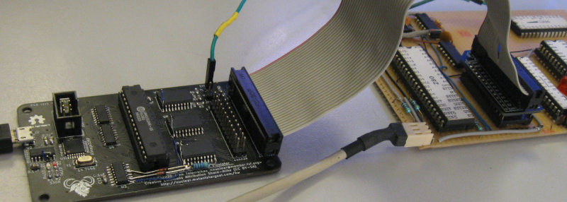
emurom photo

The purpose of emurom is to make it fast and convenient to hack code in ROMs without having to repeatedly remove and reprogram an actual ROM chip.

Emurom is a board which connects through USB to a host computer, and can be connected in place of a parallel ROM chip on a target device. It acts as a ROM chip, but holds its data in a static RAM, which can be updated at any time through the USB connection. Optionally it can provide power (5v) to the device by shorting a jumper, and it also has a lead to clip to the reset signal of the target device, to automatically reboot it when a new ROM image is uploaded.

Hardware design (kicad project) is in the root directory. The firmware for the microcontroller is located under fw, while in the emurom subdirectory, there is a UNIX program which can be used to upload a ROM image to the device, simply by running it with the name of the ROM image as a command line argument.

License

Copyright (C) 2020 John Tsiombikas nuclear@member.fsf.org

All hardware designs in this project are free/open hardware. Feel free to manufacture, sell, use, modify and/or redistribute, under the terms of the Creative Commons Attribution Share-Alike license (CC BY-SA). See LICENSE.hw for details.

All software in this project (firmware and host upload program) are free software. Feel free to use, modify and/or redistribute under the terms of the GNU General Public License version 3, or at your option any later version published by the Free Software foundation. See LICENSE.sw for details.

Download

This git repository contains the current project files and source code for emurom, but it does not include any binaries or build products.

The release archive includes the schematic PDF, gerber files for PCB manufacturing, datasheets, and pre-built binaries (firmware image and host program).

Latest release (emurom rev2):

Bill of materials

Emurom rev2 BOM:

#namedescriptionpackage
1U1ATmega328P AVR microcontrollerTQFP 32
1U2MCP2221 USB-serial converterSOIC 14
1U374HCT157 quad 2-1 multiplexerSOIC 16
2U4,U574HCT595 8-bit shift register w/3-state outputSOIC 16
1U6UM61512AK 64k static RAM (or similar 64k SRAMs)PDIP 32
3U7-U974HCT244 octal 3-state bufferSOIC 20
2C1,C222 pF ceramic capacitor0805
11C3-C130.1 uF ceramic capacitor0805
2R1,R2330 Ohm resistor0805
6R3-R84.7 kOhm resistor0805
2D1,D2LED0805
2D3,D41N4148 signal diodes0805
1Y114.7456 quartz crystal7.6x4.1mm SMD
3JP1-JP32-pin male header (jumper pins)
1J16-pin (2x3) male header or IDC conn. 2.54mm pitch
1J2molex 105017-1001 micro-USB (type B) connector
1U10,J324-pin (2x12) male header or IDC conn. 2.54mm pitch
1U11,J528-pin (2x14) male header or IDC conn. 2.54mm pitch
1J71-pin male header

Parts

58
QtyValueFootprintReferences
110.1uFCapacitor_SMD:C_0805_2012Metric_Pad1.15x1.40mm_HandSolderC3, C4, C5, C6, C7, C8, C9, C10, C11, C12, C13
64K7Resistor_SMD:R_0805_2012Metric_Pad1.15x1.40mm_HandSolderR3, R4, R5, R6, R7, R8
5VAL**emurom:mouse-bite-2mm-slotmouse-bite-2mm-slot, mouse-bite-2mm-slot, mouse-bite-2mm-slot, mouse-bite-2mm-slot, mouse-bite-2mm-slot
374HCT244Package_SO:SOIC-20W_7.5x12.8mm_P1.27mmU7, U8, U9
21N4148Diode_SMD:D_0805_2012Metric_Pad1.15x1.40mm_HandSolderD3, D4
222pFCapacitor_SMD:C_0805_2012Metric_Pad1.15x1.40mm_HandSolderC1, C2
2330RResistor_SMD:R_0805_2012Metric_Pad1.15x1.40mm_HandSolderR1, R2
274HCT595Package_SO:SOIC-16_3.9x9.9mm_P1.27mmU4, U5
114.7456Crystal:Crystal_SMD_ECS_CSM3X-2Pin_7.6x4.1mmY1
174HCT157Package_SO:SOIC-16_4.55x10.3mm_P1.27mmU3
1ATmega328P-AUPackage_QFP:TQFP-32_7x7mm_P0.8mmU1
1AVR-ISPConnector_IDC:IDC-Header_2x03_P2.54mm_VerticalJ1
1JP A13Connector_PinHeader_2.54mm:PinHeader_1x02_P2.54mm_VerticalJP3
1JP A14Connector_PinHeader_2.54mm:PinHeader_1x02_P2.54mm_VerticalJP2
1LOGOemurom:gnulogoG***
1RxLEDLED_SMD:LED_0805_2012Metric_Pad1.15x1.40mm_HandSolderD1
1SYSRSTConnector_PinSocket_2.54mm:PinSocket_1x01_P2.54mm_VerticalJ7
1TxLEDLED_SMD:LED_0805_2012Metric_Pad1.15x1.40mm_HandSolderD2
1USB_B_MicroConnector_USB:USB_Micro-B_Molex-105017-0001J2
1VCCOUTConnector_PinHeader_2.54mm:PinHeader_1x02_P2.54mm_VerticalJP1
1conn2kemurom:conn2kU10
1conn32kemurom:conn32kU11
1dip2kPackage_DIP:DIP-24_W15.24mm_SocketJ4
1dip32kPackage_DIP:DIP-28_W15.24mm_SocketJ6
1idc2kemurom:conn2kJ3
1idc32kemurom:conn32kJ5
1mcp2221Package_SO:SOIC-14_3.9x8.7mm_P1.27mmU2
1sram_um61512akPackage_DIP:DIP-32_W7.62mmU6

The 53 most common of 58 parts.

Questions

How big is the Emurom PCB?

It measures 90.6 × 77.8 mm and has 2 copper layers, 1.6 mm thick.

What parts does the Emurom use?

58 parts, built around the ATMEGA328P-AU, 74HCT244D, MCP2221-I/P and 74HCT595D. The full list of its parts is on this page, with links to each part's symbol and footprint where PCBKit's library has them.

Where can I download the Emurom KiCad files?

From the jtsiomb/emurom repository on GitHub, at the commit this page was made from: the board is emurom.kicad_pcb. PCBKit opens the board in the browser, with nothing to install.

Can I use the Emurom design in my own project?

Its repository publishes it under the CC-BY-SA-4.0 licence: you may reuse it on that licence's terms (keep the author's notice, and for a copyleft licence share your changes alike).

Similar boards

  • 2 layers235 × 158.8 mmGigatron, the printed circuit board in 3D

    Gigatron

    flypie/Gigatron

    This is a version of the files from https://gigatron.io/ altered to work on a vanilla KiCAD 5.1.6. Changes are minimal in the schematic and PCB, layout has only been changed where dimensions or orientations changed as a…

    151 parts2
  • 2 layers100 × 100 mm16MB DRAM, the printed circuit board in 3D

    16MB DRAM

    ab0tj/MiniSys

    Homebrew computer with an ISA-like bus

    35 parts7
  • 4 layers280 × 140 mmP8x alu card, the printed circuit board in 3D

    P8x alu card

    ksr/p8x

    Generated by generators/genkicad.py from the canonical geneagle netlist (CARDS["peripheral-card"]), same standard as the memory card: 4-layer (F/B signals, In1=GND, In2=VCC planes), a bypass cap above each IC, a…

    77 parts
  • 4 layers39.8 × 39.8 mmLow cost multispectral sensor, the printed circuit board in 3D

    Low cost multispectral sensor

    Matthew-Bon/low_cost_multispectral_sensor

    AS726x based sensor with USB interface.

    44 partsMIT
  • 2 layers46 × 22 mmPower Board, the printed circuit board in 3D

    Power Board

    timohueser/MyoSense

    As mentioned before the MyoSense Sensor Modules use dry stainless steel electrodes to pick up the small voltages generated by muscle activity on the skin above the monitored muscle.

    26 partsGPL-3.0
  • 2 layers100 × 72 mmHigh torque servo arm main, the printed circuit board in 3D

    High torque servo arm main

    akornsys-rdi/high-torque-servo-arm

    High torque servo arm, the system behind «Llegar a las manos» artwork

    87 partsGPL-3.0