
2 layers82 × 70 mm
NODO ACCESO
DavidManzano04/control-acceso-iot
Sistema IoT de control de acceso y asistencia docente con RFID: firmware ESP32 + Hikvision y plataforma web Flask (trabajo de grado UCEVA)
58 parts
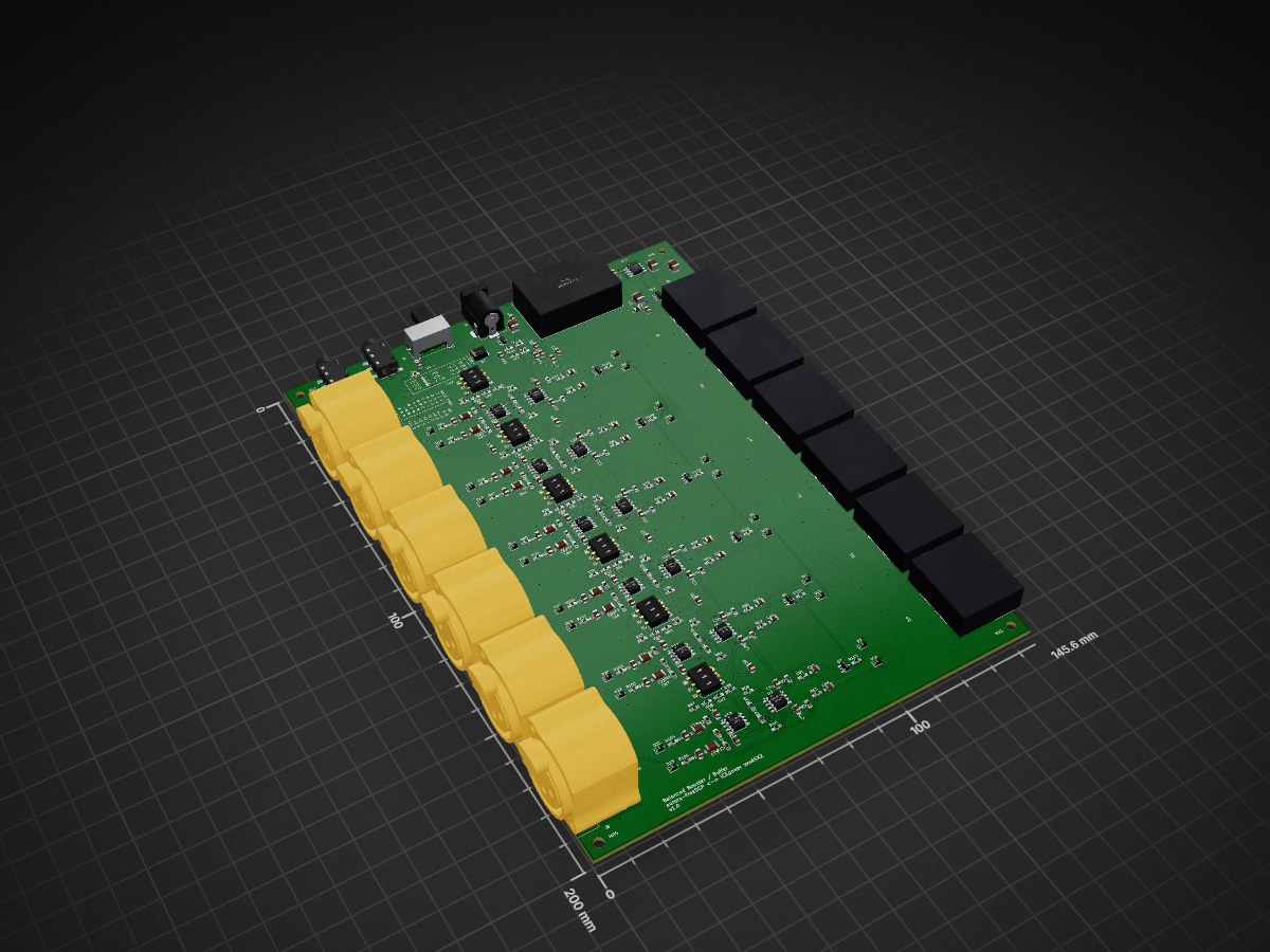
 jpsamuelson/aurora-icepower-booster
Balanced buffer / booster between aurora-freeDSP and ICEpower xxxASX2 amps.
Aurora dsp icepower booster is an open-source printed circuit board by jpsamuelson, from the jpsamuelson/aurora-icepower-booster repository on GitHub. It is a 2-layer board of 145.6 × 200 mm with 269 parts on 141 nets, routed with 1,490 tracks and 332 vias.
It is built around the TEL 5-2422, LM4562NA and PESD5V0S1BL, with the BSS138, BLM18PG221SN1 and SMBJ15CA among its other parts. Its parts include 113 resistors, 81 capacitors, 25 diodes, 15 ICs and 15 connectors. It belongs with the audio and music boards of this library.


6-Channel Balanced Audio Interface — Aurora FreeDSP → ICEpower Amplifier Modules
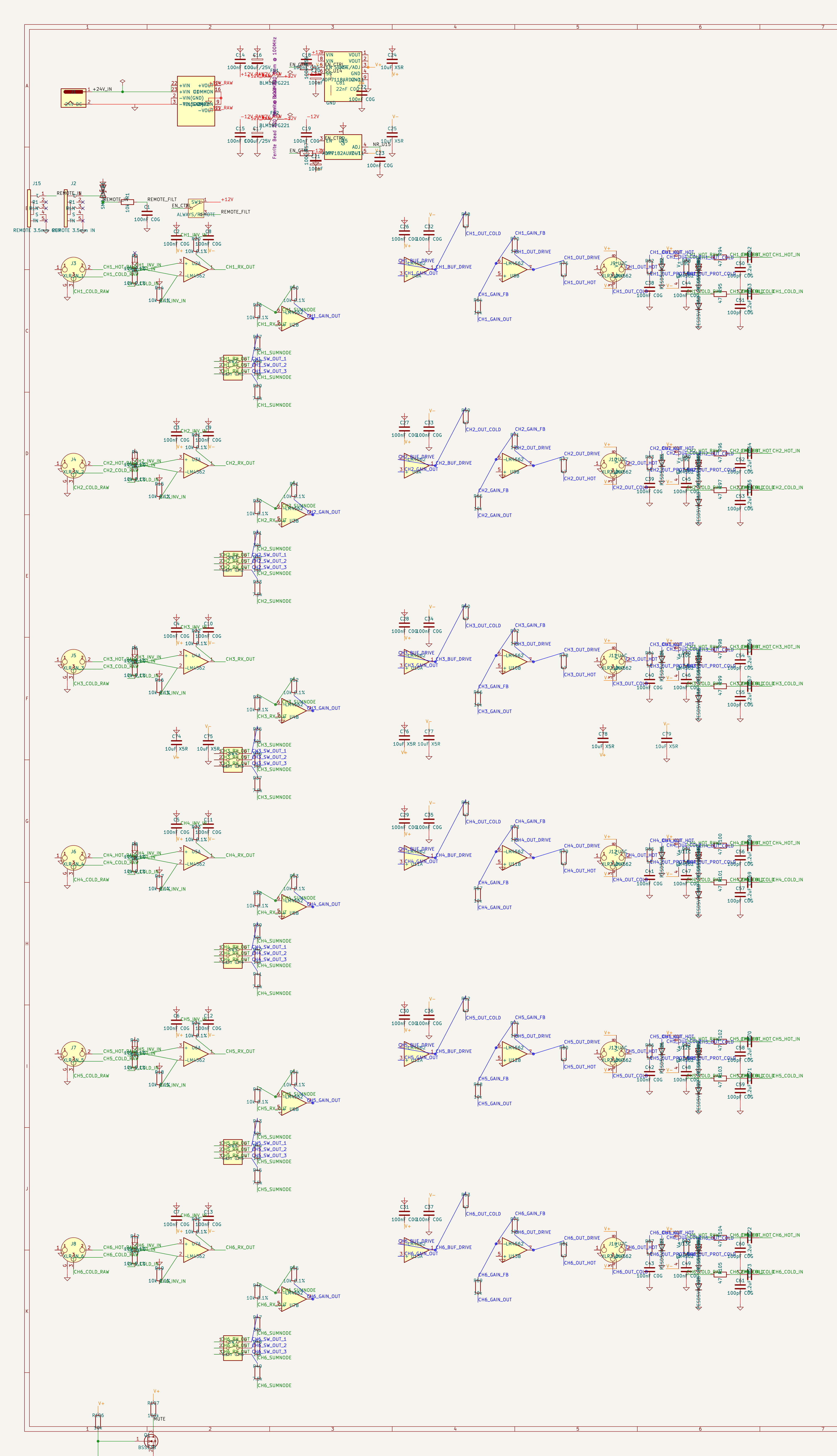
This board sits between an Aurora FreeDSP DSP processor and six ICEpower Class-D amplifier modules. It receives 6 balanced audio signals from the DSP, applies adjustable gain (0–11.3 dB), protects the signals, and outputs them as balanced XLR signals.
| Parameter | Value |
|---|---|
| Channels | 6 (identical) |
| Input | 6× XLR Female, Pin 2 = Hot, Pin 3 = Cold, Pin 1 = GND |
| Output | 6× XLR Male, Pin 2 = Hot, Pin 3 = Cold, Pin 1 = GND |
| Power Supply | 24V DC (Barrel Jack) |
| Op-Amp Supply | ±11V (low-noise LDO) |
| Gain Range | 0 dB to +11.3 dB (8 steps via DIP switch) |
| Input Impedance | ~10 kΩ balanced |
| Output Impedance | ~47Ω (series R) |
| Input CMRR | ~62 dB (4× 10kΩ 0.1% metal film) |
| SNR Target | > 100 dB |
| THD+N Target | < 0.01% @ 1 kHz |
| Remote Interface | KH-PJ-320EA-5P-SMT 3.5mm jack (Aurora FreeDSP Custom Out) |
| Manufacturing | JLCPCB, 2-Layer, FR-4, HASL, 145.6 × 200 mm |
graph LR
    DSP["Aurora FreeDSP\n(6× XLR Out)"]
    BOARD["Aurora DSP\nICEpower Booster"]
    AMP1["ICEpower #1"]
    AMP2["ICEpower #2"]
    AMP3["ICEpower #3"]
    AMP4["ICEpower #4"]
    AMP5["ICEpower #5"]
    AMP6["ICEpower #6"]
    PSU["24V DC\nPower Supply"]
    REMOTE["FreeDSP\nRemote Out"]

    DSP -->|"CH1 XLR Balanced"| BOARD
    DSP -->|"CH2 XLR Balanced"| BOARD
    DSP -->|"CH3 XLR Balanced"| BOARD
    DSP -->|"CH4 XLR Balanced"| BOARD
    DSP -->|"CH5 XLR Balanced"| BOARD
    DSP -->|"CH6 XLR Balanced"| BOARD
    PSU -->|"24V"| BOARD
    REMOTE -->|"3.5mm Enable"| BOARD
    BOARD -->|"CH1 +Gain"| AMP1
    BOARD -->|"CH2 +Gain"| AMP2
    BOARD -->|"CH3 +Gain"| AMP3
    BOARD -->|"CH4 +Gain"| AMP4
    BOARD -->|"CH5 +Gain"| AMP5
BOARD -->|"CH6 +Gain"| AMP6All 6 channels are identical. Each channel consists of 5 stages:
flowchart LR
    XIN["XLR IN\nJ3–J8"]
    ESD1["ESD Protection\nInput"]
    EMI["EMI Filter\n47Ω + 100pF"]
    DC["DC Blocking\n2.2µF C0G"]
    DIFF["Diff Receiver\nLM4562 Unit A"]
    GAIN["Gain Stage\nLM4562 Unit B"]
    MUTE["Muting\nBSS138"]
    DRV["Balanced Driver\nLM4562 (2nd IC)"]
    ZOB["Zobel\n10Ω + 100nF"]
    ESD2["ESD Protection\nOutput"]
    XOUT["XLR OUT\nJ9–J14"]

XIN --> ESD1 --> EMI --> DC --> DIFF --> GAIN --> MUTE --> DRV --> ZOB --> ESD2 --> XOUT| Stage | Function | Key Components |
|---|---|---|
| 1. ESD & EMI Filter | Overvoltage protection + RF filtering | PESD5V0S1BL, 47Ω + 100pF, 2.2µF C0G DC blocking |
| 2. Diff Receiver | Balanced → single-ended, CMRR ~62 dB | LM4562 Unit A, 4× 10kΩ 0.1% |
| 3. Gain Stage | Inverting amp, 0–11.3 dB adjustable | LM4562 Unit B, DIP switch + 3 parallel R |
| 4. Muting | Power-on pop suppression, τ = 100 ms | BSS138 N-MOSFET, RC timing |
| 5. Balanced Driver | Single-ended → balanced output | LM4562 (buffer + inverter), 47Ω series R, Zobel network |
→ Full signal chain documentation with schematics and formulas
| SW Pos 1 (30kΩ) | SW Pos 2 (15kΩ) | SW Pos 3 (7.5kΩ) | Gain (dB) |
|---|---|---|---|
| OFF | OFF | OFF | 0.0 dB |
| OFF | OFF | ON | +2.5 dB |
| OFF | ON | OFF | +4.4 dB |
| OFF | ON | ON | +6.0 dB |
| ON | OFF | OFF | +7.4 dB |
| ON | OFF | ON | +8.5 dB |
| ON | ON | OFF | +9.5 dB |
| ON | ON | ON | +11.3 dB |
$$G = \frac{R_f}{R_{in,eff}} \quad\text{with}\quad R_{in,eff} = R_{base} \parallel R_{pos1} \parallel R_{pos2} \parallel R_{pos3}$$
→ Full gain configuration details
| Parameter | Value |
|---|---|
| Board Size | 145.6 × 200 mm |
| Layers | 2 (F.Cu + B.Cu) |
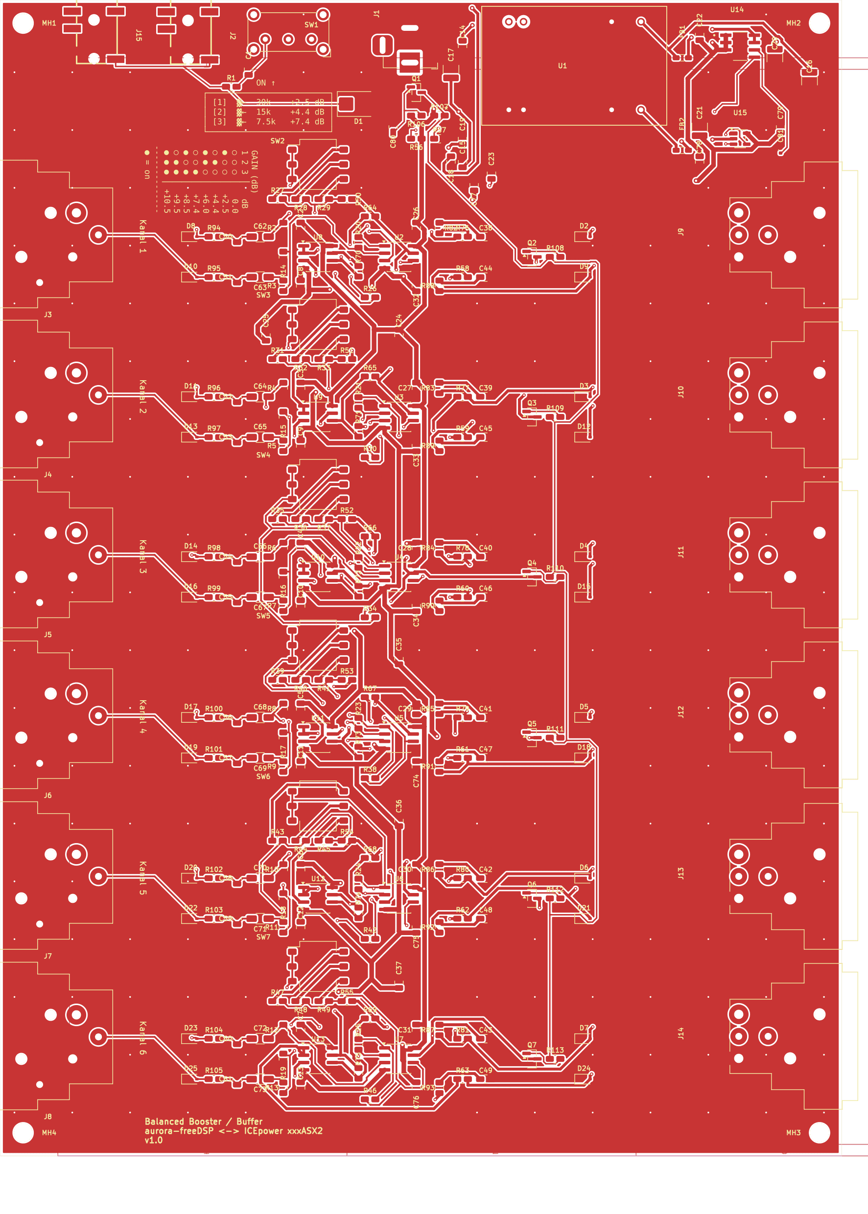
| Footprints | 269 |
| Nets | 135 in 5 net classes |
| Routing | Freerouting v2.0.1 — 1543 segments + 476 vias |
| GND Zones | F.Cu (solid connect) + B.Cu (thermal relief) |
| DRC | 0 Errors, 0 Unconnected, 198 Warnings (cosmetic) |
| Net Class | Nets | Track Width | Clearance |
|---|---|---|---|
| Default | 62 | 0.25 mm | 0.2 mm |
| Audio_Input | 30 | 0.3 mm | 0.25 mm |
| Audio_Output | 36 | 0.5 mm | 0.2 mm |
| Audio_Power | 0 | 0.8 mm | 0.2 mm |
| Power | 7 | 0.5 mm | 0.2 mm |
→ PCB layout details & DRC breakdown
Production files are ready in the production/ directory:
production/gerber/ (JLCPCB format, Protel extensions, tented vias)production/assembly/ (JLCPCB SMT assembly format)| Method | Checks | Result |
|---|---|---|
| Method 1 — OrcadPCB2 netlist, component-centric | 85/85 | ✅ |
| Method 2 — KiCad-native netlist, net-centric (pintype/pinfunction) | 177/177 | ✅ |
All component references, net names, and pin assignments in the documentation were extracted directly from the verified KiCad netlist and are sufficient to fully rebuild the schematic without the
.kicad_schfile.
| Document | Description |
|---|---|
| Signal Chain | Detailed 5-stage signal path with Mermaid diagrams, formulas, and per-stage component tables |
| Power Supply | DC/DC converter, LDOs, ferrite beads, decoupling architecture |
| Muting & Remote Control | Remote enable logic, muting timing, SPDT switch modes |
| Gain Configuration | DIP switch table, gain formula, per-channel resistor mapping |
| Component Reference | Complete BOM with all 242 symbols: R, C, D, J, SW, Q, U, FB |
| Schematic Rebuild Guide | Step-by-step wiring instructions + full 6-channel component mapping |
| PCB Layout | Net classes, DRC status, routing details |
| Research: Balanced Audio ICs | THAT1240, DRV135, SSM2143, LM4562 comparison & JLCPCB availability |
| Research: THT Precision Components | 0.1% resistors, C0G capacitors, THT sourcing guide |
This project is self-contained — all footprints and 3D models are included locally.
├── aurora-dsp-icepower-booster.kicad_pro   # Project
├── aurora-dsp-icepower-booster.kicad_sch   # Schematic
├── aurora-dsp-icepower-booster.kicad_pcb   # PCB Layout
├── aurora-dsp-icepower-booster.kicad_sym   # Local symbols
├── aurora-dsp-icepower-booster.kicad_dru   # Custom design rules
├── footprints.pretty/                      # 21 footprints (local)
│   └── 3dshapes/                           # 19 STEP 3D models
├── production/
│   ├── gerber/                             # Manufacturing data
│   └── assembly/                           # BOM + placement data
├── docs/                                   # Detailed documentation
│   ├── signal-chain.md
│   ├── power-supply.md
│   ├── muting-and-remote.md
│   ├── gain-configuration.md
│   ├── component-reference.md
│   ├── schematic-rebuild-guide.md
│   ├── pcb-layout.md
│   └── research/
│       ├── balanced-audio-ic-comparison.md
│       └── tht-precision-components.md
└── scripts/                                # Build & validation scripts
Schematic: KiCad 9 — aurora-dsp-icepower-booster.kicad_sch
Manufacturing: JLCPCB 2-Layer FR-4 HASL — Gerber files in production/gerber/
| Qty | Value | Footprint | References |
|---|---|---|---|
| 43 | 100nF C0G | C_0805_2012Metric | C1, C2, C10, C11, C12, C13, C14, C15, C18, C19, C22, C23, C26, C27, C28, C29 +27 |
| 36 | 10k 0.1% | R_0805_2012Metric | R2, R10, R11, R12, R13, R14, R15, R16, R17, R18, R19, R20, R21, R22, R23, R24 +20 |
| 24 | 47 | R_0805_2012Metric | R58, R59, R60, R61, R62, R63, R76, R77, R78, R79, R100, R101, R102, R103, R104, R105 +8 |
| 24 | PESD5V0S1BL | D_SOD-323 | D2, D10, D11, D12, D13, D14, D15, D16, D17, D18, D19, D20, D21, D22, D23, D24 +8 |
| 20 | 10k | R_0805_2012Metric | R1, R64, R65, R66, R67, R68, R69, R70, R71, R106, R108, R109, R110, R111, R112, R113 +4 |
| 12 | 10 | R_0805_2012Metric | R82, R83, R84, R85, R86, R87, R88, R89, R90, R91, R92, R93 |
| 12 | 100pF C0G | C_0805_2012Metric | C50, C51, C52, C53, C54, C55, C56, C57, C58, C59, C60, C61 |
| 12 | 2.2uF C0G | C_1206_3216Metric | C62, C63, C64, C65, C66, C67, C68, C69, C70, C71, C72, C73 |
| 12 | LM4562 | SOIC-8_3.9x4.9mm_P1.27mm | U2, U3, U4, U5, U6, U7, U8, U9, U10, U11, U12, U13 |
| 8 | 10uF X5R | C_0805_2012Metric | C24, C25, C74, C75, C76, C77, C78, C79 |
| 7 | BSS138 | SOT-23 | Q1, Q2, Q3, Q4, Q5, Q6, Q7 |
| 6 | 15k | R_0805_2012Metric | R28, R32, R36, R40, R44, R48 |
| 6 | 30k | R_0805_2012Metric | R27, R31, R35, R39, R43, R47 |
| 6 | 7.5k | R_0805_2012Metric | R29, R33, R37, R41, R45, R49 |
| 6 | XLR3_OUT | Connector_Audio:Jack_XLR_Neutrik_NC3MBH_Horizontal | J9, J10, J11, J12, J13, J14 |
| 4 | MountingHole | MountingHole_3.2mm_M3 | MH1, MH2, MH3, MH4 |
| 3 | 100k | R_0805_2012Metric | R56, R57, R107 |
| 2 | 100uF | C_1210_3225Metric | C20, C21 |
| 2 | 100uF/25V | C_1210_3225Metric | C16, C17 |
| 2 | BLM18PG221 | L_0805_2012Metric | FB1, FB2 |
| 1 | 10u | C_0805_2012Metric | C80 |
| 1 | 22nF C0G | C_0402_1005Metric | C81 |
| 1 | 24V DC | BarrelJack_Horizontal | J1 |
| 1 | ADP7118ARDZ-11 | SOIC127P600X175-9N | U14 |
| 1 | ADP7182AUJZ-11 | SOT-23-5 | U15 |
| 1 | ALWAYS/REMOTE | SW_E-Switch_EG1224_SPDT_Angled | SW1 |
| 1 | Gain CH1 | SW_DIP_SPSTx03_Slide_Omron_A6S-310x_W8.9mm_P2.54mm | SW2 |
| 1 | Gain CH2 | SW_DIP_SPSTx03_Slide_Omron_A6S-310x_W8.9mm_P2.54mm | SW3 |
| 1 | Gain CH3 | SW_DIP_SPSTx03_Slide_Omron_A6S-310x_W8.9mm_P2.54mm | SW4 |
| 1 | Gain CH4 | SW_DIP_SPSTx03_Slide_Omron_A6S-310x_W8.9mm_P2.54mm | SW5 |
| 1 | Gain CH5 | SW_DIP_SPSTx03_Slide_Omron_A6S-310x_W8.9mm_P2.54mm | SW6 |
| 1 | Gain CH6 | SW_DIP_SPSTx03_Slide_Omron_A6S-310x_W8.9mm_P2.54mm | SW7 |
| 1 | REMOTE 3.5mm IN | aurora-dsp-icepower-booster:AUDIO-SMD_KH-PJ-320EA-5P-SMT | J2 |
| 1 | REMOTE 3.5mm OUT | aurora-dsp-icepower-booster:AUDIO-SMD_KH-PJ-320EA-5P-SMT | J15 |
| 1 | SMBJ15CA | D_SMB | D1 |
| 1 | TEL5-2422 | TEL5_DUAL_TRP | U1 |
| 1 | XLR_IN_1 | Connector_Audio:Jack_XLR_Neutrik_NC3FBH2_Horizontal | J3 |
| 1 | XLR_IN_2 | Connector_Audio:Jack_XLR_Neutrik_NC3FBH2_Horizontal | J4 |
| 1 | XLR_IN_3 | Connector_Audio:Jack_XLR_Neutrik_NC3FBH2_Horizontal | J5 |
| 1 | XLR_IN_4 | Connector_Audio:Jack_XLR_Neutrik_NC3FBH2_Horizontal | J6 |
| 1 | XLR_IN_5 | Connector_Audio:Jack_XLR_Neutrik_NC3FBH2_Horizontal | J7 |
| 1 | XLR_IN_6 | Connector_Audio:Jack_XLR_Neutrik_NC3FBH2_Horizontal | J8 |
It measures 145.6 × 200 mm and has 2 copper layers, 1.6 mm thick.
269 parts, built around the TEL 5-2422, LM4562NA, PESD5V0S1BL and BSS138. The full list of its parts is on this page, with links to each part's symbol and footprint where PCBKit's library has them.
From the jpsamuelson/aurora-icepower-booster repository on GitHub, at the commit this page was made from: the board is aurora-dsp-icepower-booster.kicad_pcb and its schematic aurora-dsp-icepower-booster.kicad_sch. PCBKit opens the board in the browser, with nothing to install.
Its repository states no licence, so its author keeps all rights: ask jpsamuelson before reusing the design.
DavidManzano04/control-acceso-iot
Sistema IoT de control de acceso y asistencia docente con RFID: firmware ESP32 + Hikvision y plataforma web Flask (trabajo de grado UCEVA)

Dizzerin/Software-Defined-Radio
Quadrature sampling down converter software defined radio

pricna/Software-Defined-Radio-Receiver
Software Defined Radio receiver created for Engineering Electronics II at Walla Walla University.


Andre1Becker/GalvOS
Open-source ESP32-S3 laser show controller — built to replace proprietary OEM controllers in RGB galvo laser projectors


darshp848/bldc-controller-60v
60 V, 20 A / 80 A peak BLDC motor controller that fits the MD80 v3.0 mounting. KiCad 10, 6 layers.
