2 layers74 × 72.1 mm
ENGR357 Project v1.1
pricna/Software-Defined-Radio-Receiver
Software Defined Radio receiver created for Engineering Electronics II at Walla Walla University.
80 parts3MPL-2.0

 Dizzerin/Software-Defined-Radio24
Quadrature sampling down converter software defined radio
SDRReciever is an open-source printed circuit board by Dizzerin, from the Dizzerin/Software-Defined-Radio repository on GitHub. It is a 2-layer board of 81.3 × 33.7 mm with 67 parts on 36 nets, routed with 474 tracks and 86 vias.
It is built around the LM4562NA, SN74CBT3253D and SI5351A-B-GT, with the BSS138 and MMBT2222A-TP among its other parts. Its parts include 18 capacitors, 15 resistors, 10 connectors, 3 ICs and 3 transistors. It belongs with the AVR (ATmega, ATtiny) boards of this library.


This project is a quadrature sampling down converter software defined radio reciver for Engineering Electronics II at Walla Walla University. My partners for this project were Darius Felder and Eric Walsh. For a quick look at the final results of our project jump to results. For a quick setup guide jump to Quisk setup.
Our professor, Dr. Rob Frohne, gave us the following design objectives:
Minimum discernible signal less than 1μV
Good image rejection
Low noise figure
Inexpensive to build
Simple Design: We wanted our design to be easy to understand and construct
Ease of Construction: We wanted to build a simple radio that works
Low Cost: Our budget for this project was $30
The Software Defined Radio (SDR) receiver connects to an antenna and covers the filtering, mixing, and amplification of the desired signal. It then connects a sound card within a computer and software handles the demodulation of the signal into playable audio. The mixing is handled using an Arduino Nano running code provided to us by our Professor, Dr. Rob Frohne, which interfaces with Quisk, an SDR that controls the receiver through the Arduino. Using Quisk, the radio can be tuned to a certain frequency by adjusting the speed of the local oscillator used in the mixing process. Our budget on this project to keep with the low-cost aspect was about $30 including fabrication of the PCB and the required components.
Note: Overview section by Konrad McClure
The basics of the SDR Receiver are shown below in the block diagram, with the blue components being defined by software. An antenna picks up the radio signal and passes it through a bandpass filter. This filter will attenuate any signals outside our desired range of 6–16 MHz. This is then passed through a Tayloe Mixer, also known as the Tayloe Quadrature Product Detector. The Tayloe Mixer is a simple and efficient mixer that uses a 1:4 demultiplexer and operational amplifiers to generate the I and Q quadrature signals for demodulation. After the signal has been split into four bandbase signals, they are amplified and combined into the I and Q quadrature signals. Those signals go through a final Low-Pass filter that will attenuate signals above 100KHz in frequency, effectively smoothing the output signal. This signal is then sent via 3.5mm audio cable to the soundcard which demodulates the signal. Quisk can then read the input from the sound card and play it. Quisk also interfaces to the Arduino Nano to set the speed of the local oscillator for tuning into the desired frequency.
Note: This Theory Section is a slightly modified version of work originally written by Konrad McClure
Here is a basic block diagram of our design:


This was added to smooth out 5V power supply from USB. This will help elimate supply noise.

This device converts the 5V logic of the arduino nano to the 3.3V logic of the Si5351a for both directions.

The local oscillator we used, SI5351-AB-GT clock generator was selected largely due to the fact that Dr. Frohne has used this chip with success.

The Tayloe Mixer is a mixer design as seen in this paper by Dan Tayloe. We chose it due to its relatively simple and elegant design. It utilizes a two-channel SN74CBT multiplexer and a pair of INA821ID single gain resistor instrumentation amplifiers. To be more specific, Tayloe describes this as a "switching integrator," rather than a mixer, since a mixer normally produces both a sum and difference frequency of the RF and LO signals.

A Multiple feedback low pass filter and amplifier was used.


Complete LTSpice model:


According to the Quisk pip project description, the Quisk software is "Software Defined Radio (SDR) transceiver software. You supply radio hardware that converts signals at the antenna to complex (I/Q) data at an intermediate frequency (IF). Data can come from a sound card, Ethernet or USB. Quisk then filters and demodulates the data and sends the audio to your speakers or headphones." We used Quisk in our project for just this purpose.
To get Quisk up and running with our radio, simply:
Flash the openradio_quisk.ino file to the arduino nano microcontroller.
Start Quisk and configure a new radio. Point Quisk to the quisk_conf_openradio.py file. Alternatively you can simply copy the file to your home directory (~/.quisk_conf.py).
Note: You may need to configure the following settings in this python file:
Restart Quisk tune to your desired frequency and listen away!
See board build up plan.
Photo of our complete board:
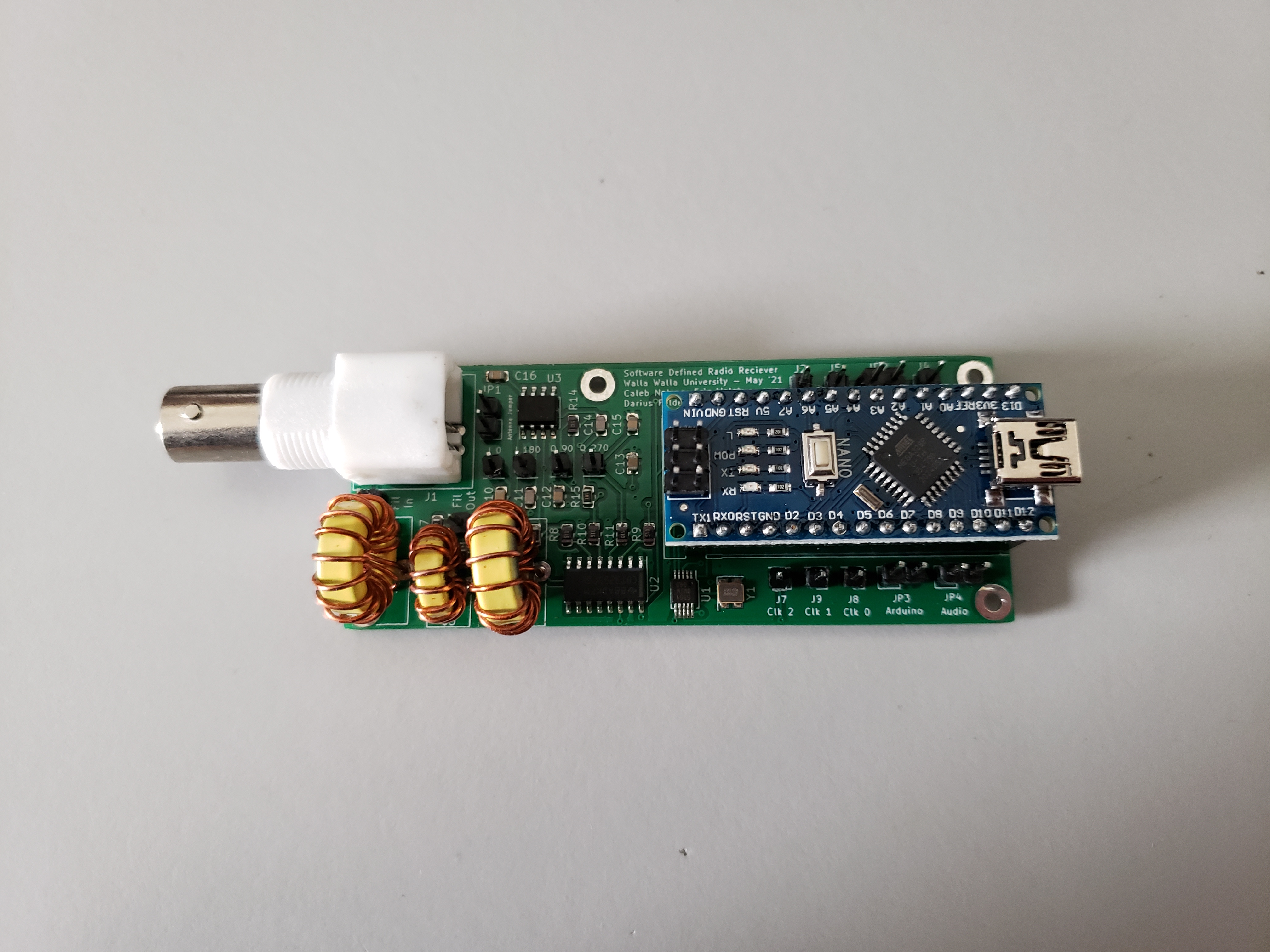
In the end, we had about 1μV of sensitivity and between 10 and 30 dB of image rejection. (Darius’ radio had about 10dB of rejection while mine had about 30dB of image rejection). Though our radios are working, they have less sensitivity than desired and when we examine the waterfall spectral display on Quisk there are some distinct lines. We believe these are from signals on the USB input, so it may be worthwhile to investigate isolating this further in future revisions.
Credit to: Dr. Frohne for his extensive help with the debugging process.
Other recommendations for future revisions include using continuous rows of pin headers for test points instead of single pin headers to ease soldering, include better ground test points (perhaps two pads to solder a wire between which ground clips can be clipped onto), moving plastic components further from surface mount chips which may need to be de-soldered, and including jumpers to allow the op amps to be powered from an alternate power source separate from the 5V circuit so additional power can be provided if desired without damaging other components.
Multiple Feedback Low-Pass Filter Design Tool
Third Order Butterworth Bandpass Filter Design Tool
Darius Felder - project partner primarily responsible for testing, simulations, and documentation
Eric Walsh - project partner primarily responsible for testing and LTSpice simulations
Dr. Frohne - class professor
Konrad McClure - previous project pioneer
Caleb Froelich - previous project pioneer
Jordyn Watkins - previous project pioneer
| Qty | Value | Footprint | References |
|---|---|---|---|
| 6 | 0.1u | Capacitor_SMD:C_0805_2012Metric | C5, C6, C7, C8, C9, C16 |
| 6 | 10k | Resistor_SMD:R_0805_2012Metric | R1, R3, R4, R5, R6, R7 |
| 4 | 51 | Resistor_SMD:R_0805_2012Metric | R8, R9, R10, R11 |
| 4 | Jumper_NC_Small | Connector_PinHeader_2.54mm:PinHeader_1x02_P2.54mm_Vertical | JP1, JP2, JP3, JP4 |
| 4 | MountingHole_Pad | MountingHole:MountingHole_2.2mm_M2_Pad | H1, H2, H3, H4 |
| 2 | 10u | Capacitor_SMD:C_0805_2012Metric | C17, C18 |
| 2 | 15p | Capacitor_SMD:C_0805_2012Metric | C11, C14 |
| 2 | 180 | Resistor_SMD:R_0805_2012Metric | R13, R15 |
| 2 | 22n | Capacitor_SMD:C_0805_2012Metric | C10, C13 |
| 2 | 330pF | Capacitor_SMD:C_0805_2012Metric | C2, C4 |
| 2 | 4.35n | Capacitor_SMD:C_0805_2012Metric | C12, C15 |
| 2 | 51k | Resistor_SMD:R_0805_2012Metric | R12, R14 |
| 2 | 820nH | Inductor_THT:L_Toroid_Vertical_L13.0mm_W6.5mm_P5.60mm | L1, L3 |
| 2 | BSS138 | Package_TO_SOT_SMD:SOT-23 | Q2, Q3 |
| 1 | 10uF | Capacitor_SMD:C_0805_2012Metric | C1 |
| 1 | 1k | Resistor_SMD:R_0805_2012Metric | R2 |
| 1 | 3.3V | Connector_PinHeader_2.54mm:PinHeader_1x01_P2.54mm_Vertical | J2 |
| 1 | 4.3V | Connector_PinHeader_2.54mm:PinHeader_1x01_P2.54mm_Vertical | J5 |
| 1 | 430nH | Inductor_THT:L_Toroid_Vertical_L10.0mm_W5.0mm_P5.08mm | L2 |
| 1 | 5V | Connector_PinHeader_2.54mm:PinHeader_1x01_P2.54mm_Vertical | J4 |
| 1 | 620pF | Capacitor_SMD:C_0805_2012Metric | C3 |
| 1 | Arduino_Nano_v3.x | Module:Arduino_Nano | A1 |
| 1 | AudioJack3 | Connector_Audio:35RAPC4BHN2 | J14 |
| 1 | CLK_0 | Connector_PinHeader_2.54mm:PinHeader_1x01_P2.54mm_Vertical | J8 |
| 1 | CLK_1 | Connector_PinHeader_2.54mm:PinHeader_1x01_P2.54mm_Vertical | J9 |
| 1 | CLK_2 | Connector_PinHeader_2.54mm:PinHeader_1x01_P2.54mm_Vertical | J7 |
| 1 | CX3225SB | Crystal:Crystal_SMD_Abracon_ABM8G-4Pin_3.2x2.5mm | Y1 |
| 1 | Conn_Coaxial | Connector_Coaxial:BNC_Amphenol_B6252HB-NPP3G-50_Horizontal | J1 |
| 1 | FIL_IN | Connector_PinHeader_2.54mm:PinHeader_1x01_P2.54mm_Vertical | J3 |
| 1 | FIL_OUT | Connector_PinHeader_2.54mm:PinHeader_1x01_P2.54mm_Vertical | J6 |
| 1 | I_0 | Connector_PinHeader_2.54mm:PinHeader_1x01_P2.54mm_Vertical | I 0 |
| 1 | I_180 | Connector_PinHeader_2.54mm:PinHeader_1x01_P2.54mm_Vertical | I 180 |
| 1 | LM4562 | Package_SO:SOIC-8_3.9x4.9mm_P1.27mm | U3 |
| 1 | LOGO | Imported_Footprints:Dolphin | G*** |
| 1 | MMBT2222A-TP | digikey-footprints:SOT-23-3 | Q1 |
| 1 | Q_270 | Connector_PinHeader_2.54mm:PinHeader_1x01_P2.54mm_Vertical | Q 270 |
| 1 | Q_90 | Connector_PinHeader_2.54mm:PinHeader_1x01_P2.54mm_Vertical | Q 90 |
| 1 | SN74CBT3253 | Package_SO:SOIC-16_3.9x9.9mm_P1.27mm | U2 |
| 1 | Si5351A-B-GT | Package_SO:MSOP-10_3x3mm_P0.5mm | U1 |
It measures 81.3 × 33.7 mm and has 2 copper layers, 1.6 mm thick.
67 parts, built around the LM4562NA, SN74CBT3253D, SI5351A-B-GT and BSS138. The full list of its parts is on this page, with links to each part's symbol and footprint where PCBKit's library has them.
From the Dizzerin/Software-Defined-Radio repository on GitHub, at the commit this page was made from: the board is KiCad PCB Schematic files/SDR_Schematic_and_PCB_files/SDRReciever.kicad_pcb. PCBKit opens the board in the browser, with nothing to install.
Its repository states no licence, so its author keeps all rights: ask Dizzerin before reusing the design.
pricna/Software-Defined-Radio-Receiver
Software Defined Radio receiver created for Engineering Electronics II at Walla Walla University.


brucemack/sdr2
This is a homebrew SDR rig with no dependency on external computers/soundcards/etc.


Erhannis/rf_switchboard
KiCAD pcb; whole heap of rf-related modules so I can figure out what works and how.


KonradMcClure/SDR_Receiver
Software Defined Radio Receiver designed together with Caleb Froelich (https://github.com/froeca) for our Walla Walla University Electronics II project.

gmtii/Prototipo-R820T2
Proyecto 'breakout' de un R820T2 más un QSD para obtener salida IQ directamente a la tarjeta de sonido del PC. La idea es experimentar con el R820T2 y un QSD cuya frecuencia de refencia es 4X a la de demodulación…