2 layers98 × 84.1 mm
 jonkster/biot1
Code for simple biot nodes.
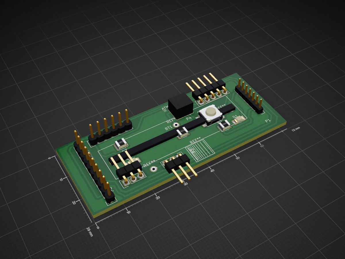
Biot node is an open-source printed circuit board by jonkster, from the jonkster/biot repository on GitHub, published under the MIT licence. It is a 2-layer board of 72 × 29 mm with 21 parts on 27 nets, routed with 169 tracks and 3 vias.
Its parts include 6 connectors, 3 resistors, 2 diodes, 1 IC and 1 switch. It belongs with the SAM D and SAM boards of this library.
Experimental code for a sensor network using ATMEL atsamr21g microcontrollers.
#About Biotz
Biotz nodes are small devices that gather and relay data about where they are physically located (eg their orientation in space, current movement etc). A group of Biotz nodes can be joined into a network and can provide information about complex movements of an assembly of parts.
For example, a human body may be considered as an assembly of various limbs. If a number of Biotz nodes are attached to locations around the body, the movement of the limbs can be monitored or recorded.
The prototype Biotz nodes were initially implemented using ATSAMR21ZLL-EK and ATSAMR21-XPRO boards, the latest version uses an ATSAMR21B-MZ210PA module and MPU9250 IMU device.
The nodes run a forked version of RIOT OS (see https://github.com/RIOT-OS/RIOT for the 'real' RIOT not my hacked up one). My forked version is at https://github.com/jonkster/RIOT and is forked to allow me to support the (currently) unsupported ATSAMR21ZLL-EK boards, the ATSAMR21B-MZ210PA module and the MPU9250 IMU device and also some customised bits I have added to the ATSAMR21-XPRO boards. NB the coding standard for my changes is not production quality and shouldn't be pushed back into the 'real' RIOT without significant refactoring - my stuff is prototype/proof of concept only!).
The nodes communicate using 6lowPAN with an edge router (currently an ATSAMR21-ZLLK board with a SLIP network interface to the wider network). The edge router is the root of a number of Biotz sensor devices.
This stuff is very experimental and a work in progress. Code quality (my code anyway) ranges from crap to even worse. You have been warned. :)
Current Structure
├── biot-applications
│   ├── biot - the sensor node code for the ZLL-EK and XPRO boards
│   ├── router - the edge router code
│   ├── modules - components common to the router and sensor nodes
│   └── utils - some stuff to assist flashing and working with the boards (cruddy but handy)
├── biot-broker - a nodejs based web service run on the PC that provides information on the Biotz network to other applications
└── biot-interface - a browser based user interface to the Biotz network
| Qty | Value | Footprint | References |
|---|---|---|---|
| 2 | 39 | Resistors_SMD:R_1210 | R2, R3 |
| 1 | 1.5V | atmelSAM:AAA_x1_Battery_Holder | BT1 |
| 1 | 10k | Resistors_SMD:R_1210 | R1 |
| 1 | ATMEL-CORTEX | atmelSAM:ATMEL_cortex_header_smd | P4 |
| 1 | ATSAMR21B | Pin_Headers:Pin_Header_Straight_1x07_Pitch2.00mm | P1 |
| 1 | ATSAMR21B-TEST-POINTs | Pin_Headers:Pin_Header_Straight_1x05 | P2 |
| 1 | FTDI/Serial | Pin_Headers:Pin_Header_Straight_1x06 | P5 |
| 1 | MPU9250-Breakout | Pin_Headers:Pin_Header_Straight_1x10 | U1 |
| 1 | On/Off Header | Pin_Headers:Pin_Header_Straight_1x03 | P6 |
| 1 | PWR | LEDs:LED_1206 | D2 |
| 1 | RESET | Buttons_Switches_SMD:SW_SPST_EVPBF | SW1 |
| 1 | SIGNAL | LEDs:LED_1206 | D1 |
| 1 | UP_CONVERTOR | Pin_Headers:Pin_Header_Straight_1x03 | P3 |
The 14 most common of 21 parts.
It measures 72 × 29 mm and has 2 copper layers, 1.6 mm thick.
21 parts. The full list of its parts is on this page, with links to each part's symbol and footprint where PCBKit's library has them.
From the jonkster/biot repository on GitHub, at the commit this page was made from: the board is hardware/biot_node_0.2/biot-node.kicad_pcb. PCBKit opens the board in the browser, with nothing to install.
Its repository publishes it under the MIT licence: you may reuse it on that licence's terms (keep the author's notice, and for a copyleft licence share your changes alike).


gusmanb/logicanalyzer
24 channel, 100Msps logic analyzer hardware and software

mntmn/amiga2000-gfxcard
MNT VA2000, an Open Source Amiga 2/3/4000 Graphics Card (Zorro II/III), written in Verilog


hackclub/OnBoard
💡 Join 1,000 teenagers and make your first PCB with a $100 grant!

drandyhaas/KiCadRoutingTools
A set of Python/Rust tools to aid routing in KiCad

Arrow-air/project-quiver
Project Quiver documentation, designs, and project artifacts.

