4 layers57.2 × 179.7 mm
Optical
gustebeast/public-steel-guitar
A pedal steel guitar you can build yourself, from parts anyone can buy.
287 partsCERN-OHL-S-2.0

 JonasE99/HCP-Bridge1
🚧 WIP – not yet manufactured or tested. KiCad PCB (one per door) connecting Hörmann series 4 garage door operators (ProMatic/SupraMatic, BUS/RJ12) to Loxone via ESP32-S3 and Wi-Fi. Hardware only – intended to run the existing HCPBridgeMqtt firmware by Gifford47.
HCP Bridge is an open-source printed circuit board by JonasE99, from the JonasE99/HCP-Bridge repository on GitHub. It is a 2-layer board of 36 × 72 mm with 53 parts on 32 nets, routed with 321 tracks and 66 vias.
It is built around the ESP32-S3-WROOM-1-N8R2, THVD1406DRL and DSS16, with the BSMD1206-020-48V, SM712 and SMAJ33CA among its other parts. Its parts include 16 resistors, 10 capacitors, 10 diodes, 3 ICs and 2 connectors. It belongs with the radio and wireless and interfaces and adapters boards and the ESP32 boards of this library.


⚠ Work in progress – rev 0.1 has not been manufactured or tested yet. Schematic and layout are complete and checked (ERC 0 errors, DRC 0 errors), but no board has been built or run on an operator so far. Build at your own risk; results of the first build will be added here.
A small board (one per door) that plugs into the BUS port (RJ12) of a Hörmann series 4 garage door operator (ProMatic 4, SupraMatic E/P 4). It acts as a UAP1-HCP expansion module towards the operator and exposes the door via Wi-Fi. Loxone talks to it over plain HTTP, no extra server needed (see below).
Firmware: This repository contains the hardware only. The board is meant to run the existing
third-party open-source firmware HCPBridgeMqtt by Gifford47
(environment HCP_Giffordv2, provides web UI, HTTP API and MQTT). The board uses the same pins
as the original ESP32-S3 boards, so the firmware runs unchanged. Please direct firmware questions
to that project.
Status rev 0.1 (2026-10-14): ERC 0 errors, DRC 0 errors (4 warnings: footprint silkscreen at the board edge, trimmed by the manufacturer).
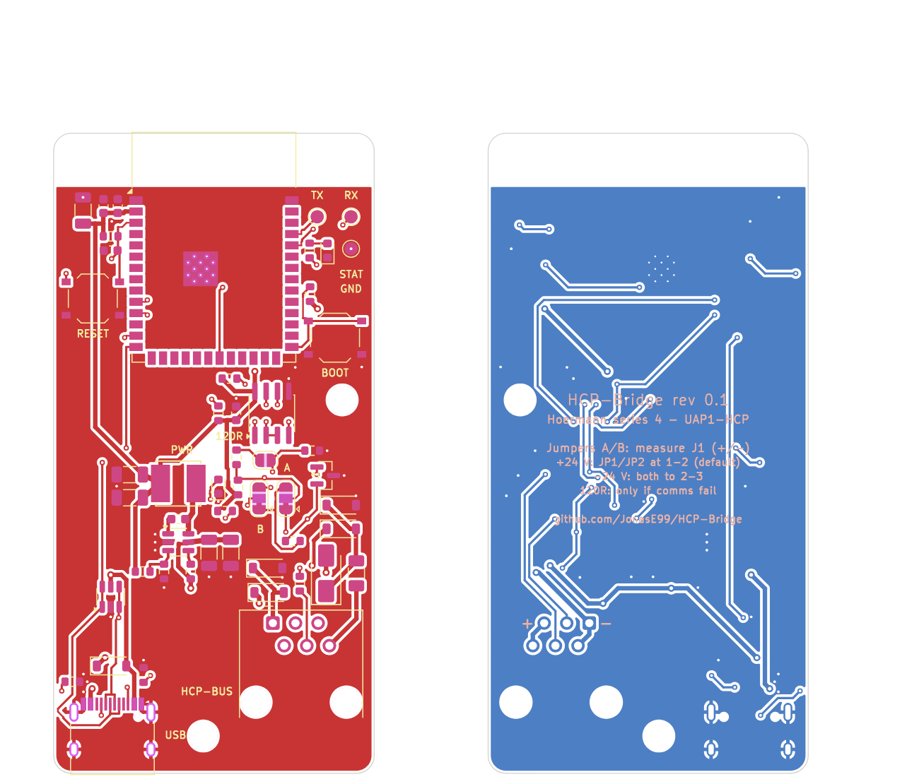
| Size | 36 × 72 mm, 2 layers, 1.6 mm, 2 × M3 |
| Power | from the bus (24 V, approx. 20–40 mA) or USB-C (5 V) |
| Radio | ESP32-S3-WROOM-1-N8R2 (PCB antenna at the top edge, no copper underneath) |
| RS-485 | TI THVD1406, automatic direction control via TX (the firmware uses TX/RX only) |
| Protection | 200 mA PTC fuse, TVS SMAJ33CA, SM712 + 10 Ω on A/B, ESD protection on USB |
| Regulator | TI LMR51610 (4–65 V, 1 A) to 3.3 V, laid out following the TI layout guidelines |
| Pins | RS-485 TX = GPIO17, RX = GPIO18, status LED = GPIO13 (as HCP_Giffordv2) |
RJ12 cables exist as straight and crossed versions, and the pin 1 side of the jack was derived from documentation. Reversed, +24 V would end up on GND and A/B would be swapped. Therefore:
Setting A/B – one measurement is enough: cable and jack can only swap the wires mirrored (1↔6, 2↔5, 3↔4), so power and data always flip together. With the bridge plugged in and the operator powered, measure on the bottom side at the solder pins of the RJ12 jack J1: red probe on the pin marked "+" (pin 5, outer pin), black probe on the pin marked "−" (pin 1, outer pin on the other end):
| Reading at J1 (+ against −) | JP1 and JP2 |
|---|---|
| approx. +24 V | keep at 1-2 (default) |
| approx. −24 V | resolder both to 2-3 |
The rule is also printed on the bottom side. Bus pinout at the operator according to HCPBridgeMqtt: 1/2 GND, 3 B−, 4 A+, 5/6 +24 V.
hardware/kicad/        KiCad 9 project HCPBridge.kicad_pro (schematic, PCB, own footprints)
hardware/fabrication/  schematic PDF, Gerber ZIP, BOM, LCSC order file, JLCPCB BOM + CPL, assembly drawing, ERC/DRC
docs/ board renderhardware/fabrication/HCPBridge-gerber.zip to JLCPCB (2 layers, 1.6 mm,
lead-free HASL; 5 pcs is the minimum).hardware/fabrication/lcsc-order.xlsx (or lcsc-order.csv). When asked to assign the columns,
choose LCSC Part Number → LCSC Part Number and Quantity → Quantity. Quantity is the
quantity per board; enter the number of boards (e.g. 3 = 2 doors + 1 spare) as the order
multiplier in the BOM tool. The column Total for 3 boards + spare is for checking only (it
adds 5 spare pieces of each small 0603 part, which tend to get lost when hand soldering), do
not assign it. LCSC rounds up to its minimum order quantities. bom.csv is the per-board list
with reference designators. Solder jumpers and test points are copper only.jlcpcb-bom.csv (BOM) and
jlcpcb-cpl.csv (pick and place) in the PCB assembly step. Rotations and reference points were
derived from the LCSC/EasyEDA footprints. Check D8, F1, L1 and U1 in the JLC placement preview:
their EasyEDA data could not be compared (pin 1 of D8/U1 must match the marking on the board).
J1 (RJ12) is a through-hole part; select it only if you also order through-hole assembly.hardware/fabrication/assembly.pdf.HCP_Giffordv2 (ESP32-S3, TX 17 / RX 18, LED 13, PSRAM). Connect USB-C to the
PC; if the ESP32 is not detected: hold BOOT, press RESET.http://192.168.4.1, then assign a fixed
IP in your router. Set a password in the web UI (see Loxone).Do not connect USB (PC) and the bus at the same time if PC and operator are earthed differently.
The commands are simple GET requests. With a web password set, the bridge asks for basic auth
(user admin); in Loxone use the address http://admin:<password>@<ip>.
Virtual output "Garage door 1", address http://admin:<pw>@192.168.x.y, commands:
| Command | Request on ON |
|---|---|
| Open | /command?action=1 |
| Close | /command?action=0 |
| Stop | /command?action=2 |
| Toggle (impulse) | /command?action=8 |
| Half open | /command?action=4 |
| Venting | /command?action=3 |
| Toggle light | /command?action=5 |
| Position (0–100) | /command?action=7&position=<v> (analog) |
Virtual HTTP input "Garage door 1 status", URL http://admin:<pw>@192.168.x.y/status, polling
every 2–5 s. Command recognition:
| Value | Command recognition | Meaning |
|---|---|---|
| Position | "currentPosition":\v | 0 = closed … 100 = open |
| State | "state":\v | 0 open, 1 opening, 2 closed, 3 closing, 4 half open, 5/6 venting, 7 moving to half, 8 stopped |
| Light | "light":\v | 1 = on (true) |
| Bus OK | "valid":\v | 1 = operator responds |
Gate block: set the Loxone "Gate" block to "subsequent control" and connect its outputs Op/Cl
(or Tg) to the Open/Close (or Toggle) commands of the virtual output. Feedback comes from the HTTP
input: end position open = state 0, end position closed = state 2, the position directly from
currentPosition / 100. The exact inputs and outputs of the block are described in the Loxone
documentation: https://www.loxone.com/enen/kb/gate/. Please double-check in Loxone Config; this
mapping has not been tested on a real Miniserver yet.
docs/PCB/vladimirzrnic)| Qty | Value | Footprint | References |
|---|---|---|---|
| 5 | DSS16 | Diode_SMD:D_SOD-123 | D2, D3, D4, D5, D6 |
| 4 | 100n | Capacitor_SMD:C_0603_1608Metric | C3, C6, C8, C9 |
| 4 | 10k | Resistor_SMD:R_0603_1608Metric | R10, R11, R12, R13 |
| 3 | 22u 25V | Capacitor_SMD:C_1206_3216Metric | C4, C5, C7 |
| 2 | 10R | Resistor_SMD:R_0603_1608Metric | R5, R6 |
| 2 | 1k | Resistor_SMD:R_0603_1608Metric | R4, R14 |
| 2 | 2u2 100V | Capacitor_SMD:C_1206_3216Metric | C1, C2 |
| 2 | 4k7 | Resistor_SMD:R_0603_1608Metric | R7, R8 |
| 2 | 5k1 | Resistor_SMD:R_0603_1608Metric | R15, R16 |
| 2 | M3 | MountingHole:MountingHole_3.2mm_M3 | H1, H2 |
| 1 | 100k | Resistor_SMD:R_0603_1608Metric | R1 |
| 1 | 120R | Resistor_SMD:R_0603_1608Metric | R9 |
| 1 | 120R | Jumper:SolderJumper-2_P1.3mm_Open_RoundedPad1.0x1.5mm | JP3 |
| 1 | 1u | Capacitor_SMD:C_0603_1608Metric | C10 |
| 1 | 200mA | Fuse:Fuse_1206_3216Metric | F1 |
| 1 | 22k1 1% | Resistor_SMD:R_0603_1608Metric | R3 |
| 1 | 22uH | HCPBridge:L_Sunlord_SWPA5040S | L1 |
| 1 | 69k8 1% | Resistor_SMD:R_0603_1608Metric | R2 |
| 1 | A select | Jumper:SolderJumper-3_P1.3mm_Bridged12_RoundedPad1.0x1.5mm | JP1 |
| 1 | B select | Jumper:SolderJumper-3_P1.3mm_Bridged12_RoundedPad1.0x1.5mm | JP2 |
| 1 | BOOT | Button_Switch_SMD:SW_Push_1P1T_XKB_TS-1187A | SW2 |
| 1 | ESP32-S3-WROOM-1-N8R2 | RF_Module:ESP32-S3-WROOM-1 | U3 |
| 1 | ESP_RXD0 | TestPoint:TestPoint_Pad_D1.5mm | TP2 |
| 1 | ESP_TXD0 | TestPoint:TestPoint_Pad_D1.5mm | TP1 |
| 1 | GND | TestPoint:TestPoint_Pad_D1.5mm | TP3 |
| 1 | LMR51610XDBVR | Package_TO_SOT_SMD:SOT-23-6 | U1 |
| 1 | RESET | Button_Switch_SMD:SW_Push_1P1T_XKB_TS-1187A | SW1 |
| 1 | RJ12 HCP bus | HCPBridge:RJ12_Molex_95501-2661_Horizontal | J1 |
| 1 | SM712 | Package_TO_SOT_SMD:SOT-23 | D8 |
| 1 | SMAJ33CA | Diode_SMD:D_SMA | D1 |
| 1 | THVD1406DR | Package_SO:SOIC-8_3.9x4.9mm_P1.27mm | U2 |
| 1 | USB-C | Connector_USB:USB_C_Receptacle_HRO_TYPE-C-31-M-12 | J2 |
| 1 | USBLC6-2SC6 | Package_TO_SOT_SMD:SOT-23-6 | D10 |
| 1 | blue | LED_SMD:LED_0603_1608Metric | D9 |
| 1 | green | LED_SMD:LED_0603_1608Metric | D7 |
It measures 36 × 72 mm and has 2 copper layers, 1.6 mm thick.
53 parts, built around the ESP32-S3-WROOM-1-N8R2, THVD1406DRL, DSS16 and BSMD1206-020-48V. The full list of its parts is on this page, with links to each part's symbol and footprint where PCBKit's library has them.
From the JonasE99/HCP-Bridge repository on GitHub, at the commit this page was made from: the board is hardware/kicad/HCPBridge.kicad_pcb and its schematic hardware/kicad/HCPBridge.kicad_sch. PCBKit opens the board in the browser, with nothing to install.
Its repository states no licence, so its author keeps all rights: ask JonasE99 before reusing the design.
gustebeast/public-steel-guitar
A pedal steel guitar you can build yourself, from parts anyone can buy.

tombueng/LuxDMX
Open-source Art-Net / sACN (E1.31) → DMX512 gateway for ESP32 / ESP32-S3 / Ethernet. Live web UI shows all 512 channels in real time, flags console conflicts, and drives galvanically-isolated DMX.


EdgeCoil/wiegand-bridge
ESP32-S3 Wiegand reader bridge for Home Assistant: 4-layer board, BOM and ESPHome firmware.

LeeSpo/portable-display-epass-EVT1-minboot-r1
当前自研硬件为 38 × 64 mm、四层 split-power 工程候选,尚未放行生产。

htumanyan/navien
Navien water heater wire protocol for communication with NaviLink and other attached devices


mhered/KiCAD_udemy_course
My notes on the course "PCB design with KiCAD - updated for KiCAD 9" by Dr Peter Dalmaris in Udemy