2 layers20 × 29.7 mm
Beacon WirelessCharge
vasimv/Everytag
Airtag/Google FMDN tag emulation firmware, fully configurable through BLE
68 parts57GPL-3.0

 jkapala/bleDemoPcb
This repo is for the BLE Demo project by J. Kapala.
Ble module is an open-source printed circuit board by jkapala, from the jkapala/bleDemoPcb repository on GitHub. It is a 4-layer board of 107.5 × 60 mm with 207 parts on 152 nets, routed with 2,111 tracks and 618 vias.
It is built around the DLF162500LT-5028A1, MX25L12833FM2I-10G and CAT24C256LI, with the LD39200PU33R, LDL112PV18R and EXB-38VR000V among its other parts. Its parts include 80 capacitors, 54 resistors, 19 connectors, 16 diodes and 8 ICs. It belongs with the radio and wireless boards and the STM32 boards of this library.


This project started with the goal of building a circuit around the STM32 architecture and incorporate various features to evaluate them, which are called out in the Specifications document. A major goal of the project was also to document the project here, making sure to share my progress and use version control. Namely, I wanted to build a board to utilize BLE/WiFi directly, using a PIFA PCB or ceramic chip antenna, instead of using a Wireless module PCB as I have done in the past. As that is the primary goal of the project, other features were secondary but I was able to incorporate a lot of the initial specifications I made and even add some that could lend themselves to a compelling demo of the board. Unfortunately, the STM line of chips does not support WiFi so it was decided that it should be exluded from the project and BLE will be the primary wireless protocol used.
The firmware can be located at this repository: https://github.com/jkapala/bleDemoFirmware
System Diagram

The Design Output document is done! I have now edited it and reviewed it so that it is now a complete draft that matches the layout and schematic. The schematic has also been reviewed and edited to fix little things and improve readibility. As well, a few changes were made to the schematic and layout. Namely, a header to access the USB VBUS rail after the current sense resitor has been added, a ground pin has been added to the analog input channel header, and the ESD diodes for the SD card were swapped for ones with lower breakdown/clamping voltage.
At this stage, I consider all the design files to be in good standing and in agreement with each other. The next step will be to generate a BOM and scrutinize the pinouts of the selected components to the schematics/layout files.
In summary, I believe this commit is a complete draft of both the schematic, layout, and design output.
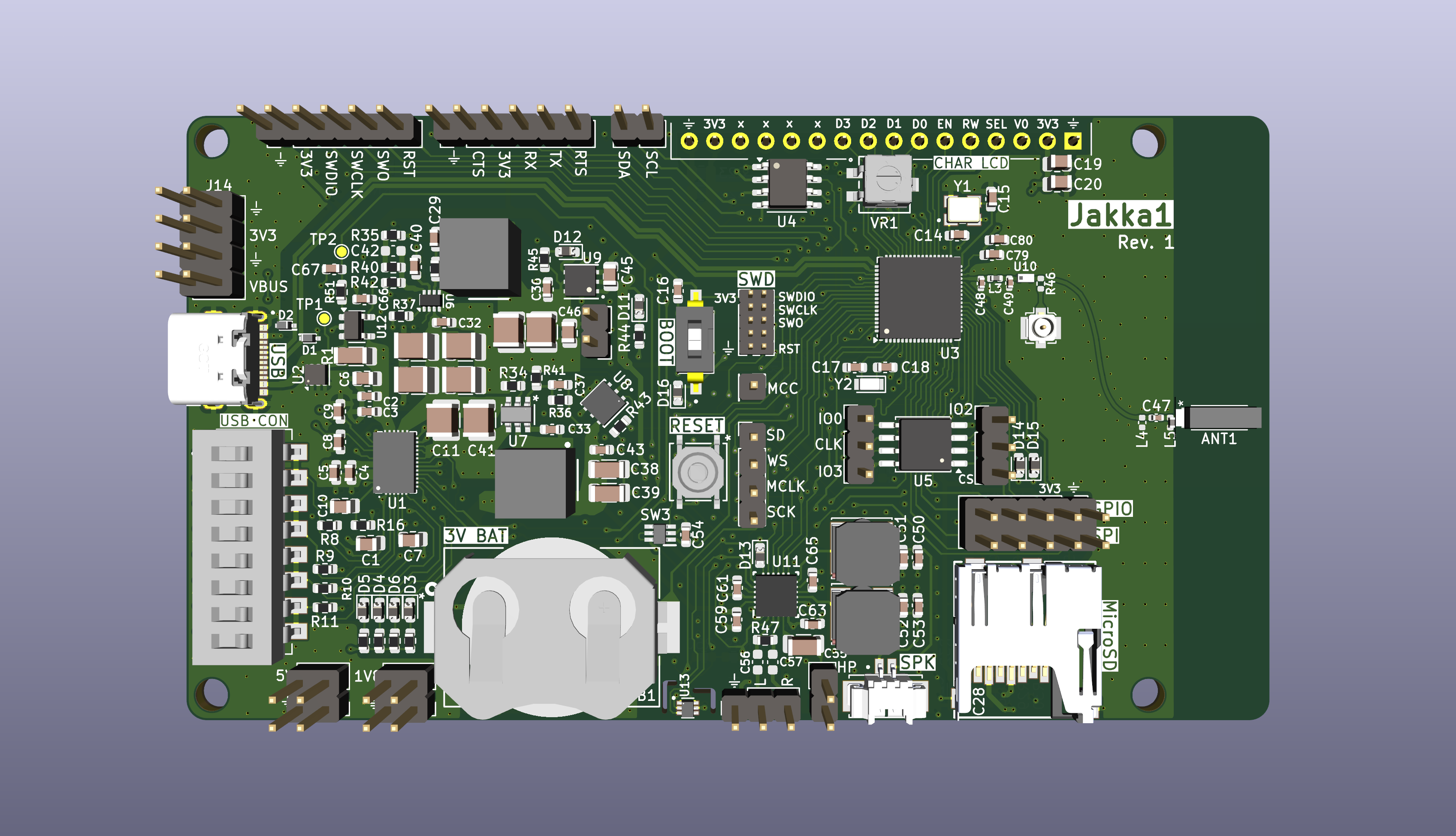
Top View
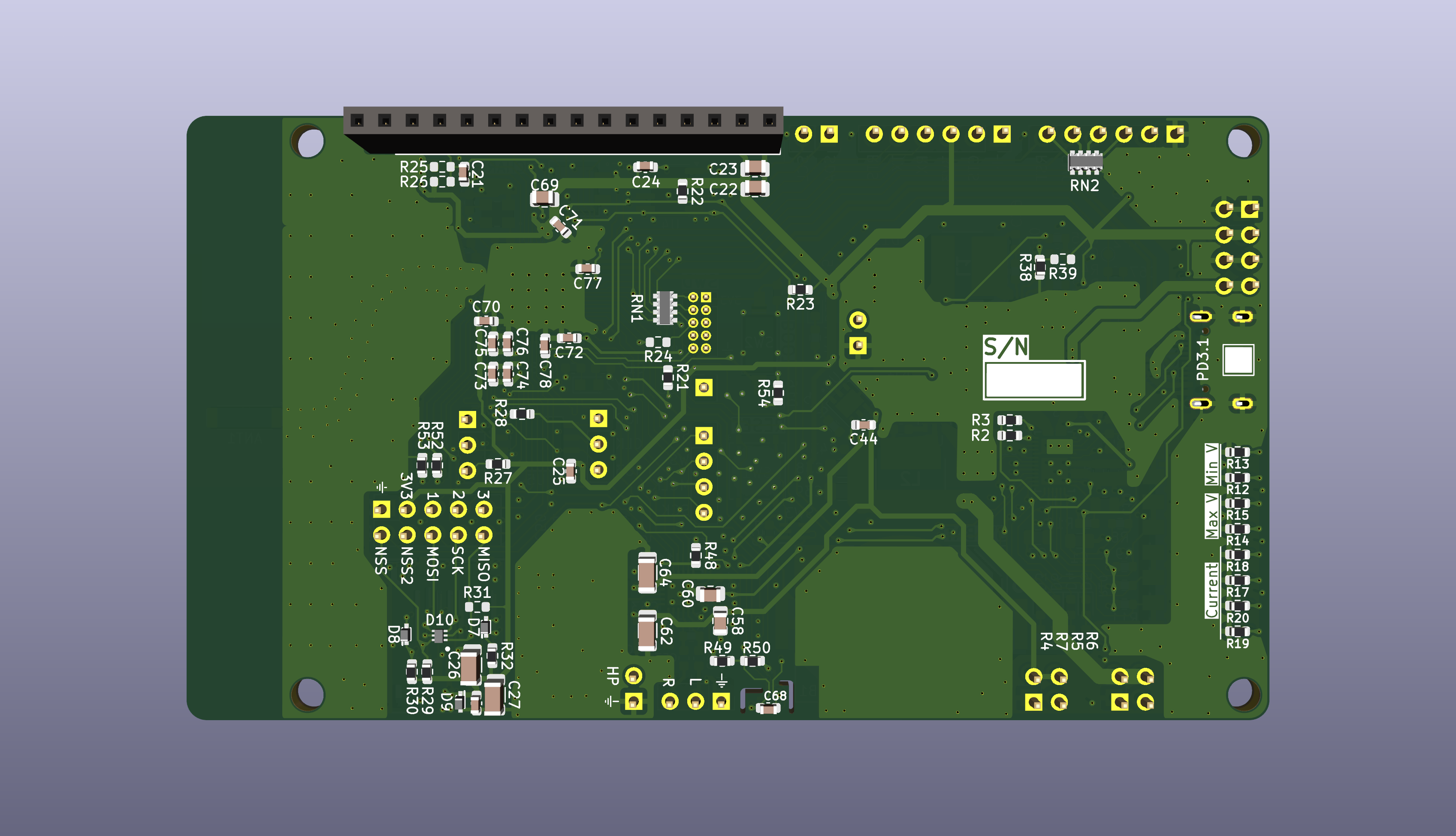
Bottom View
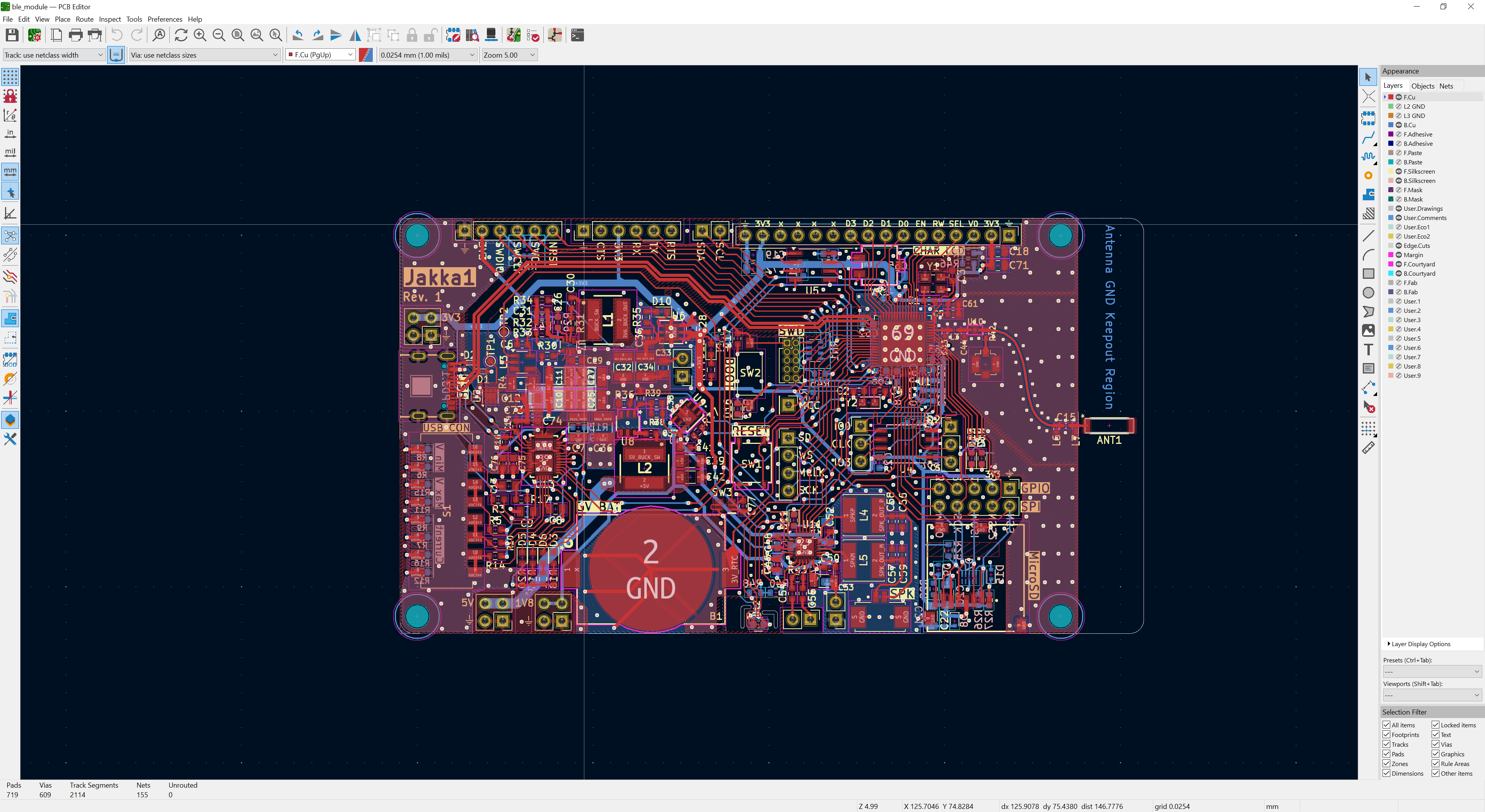
Layer View
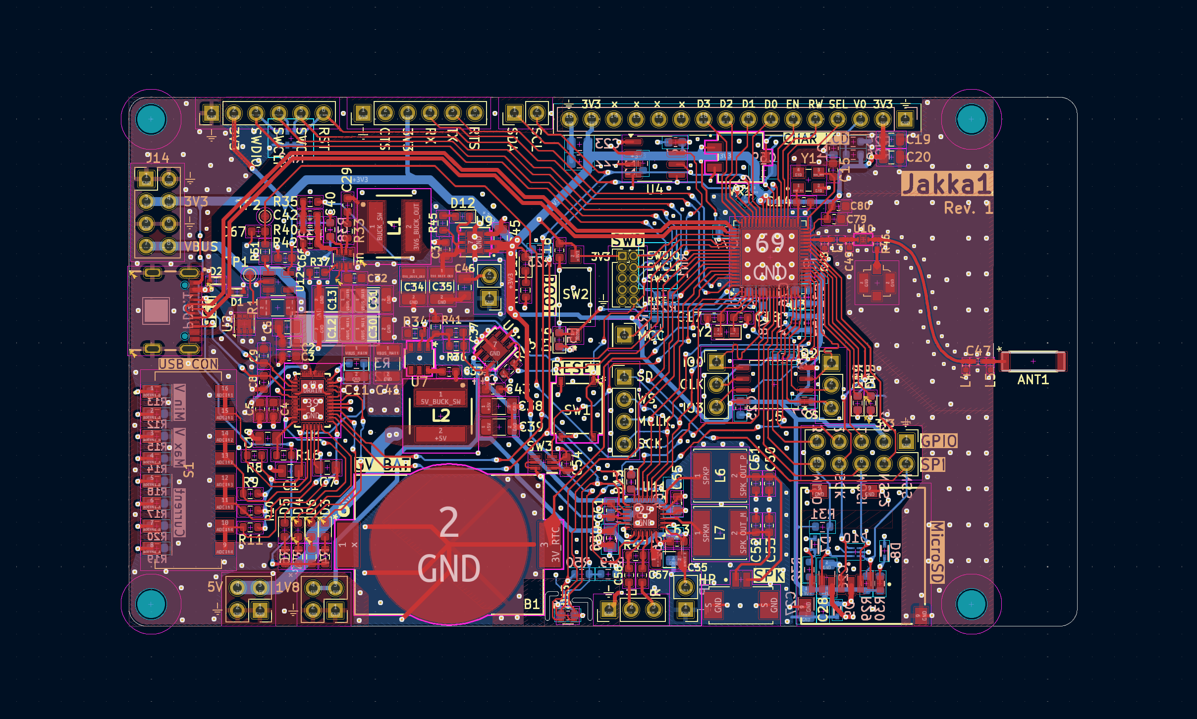
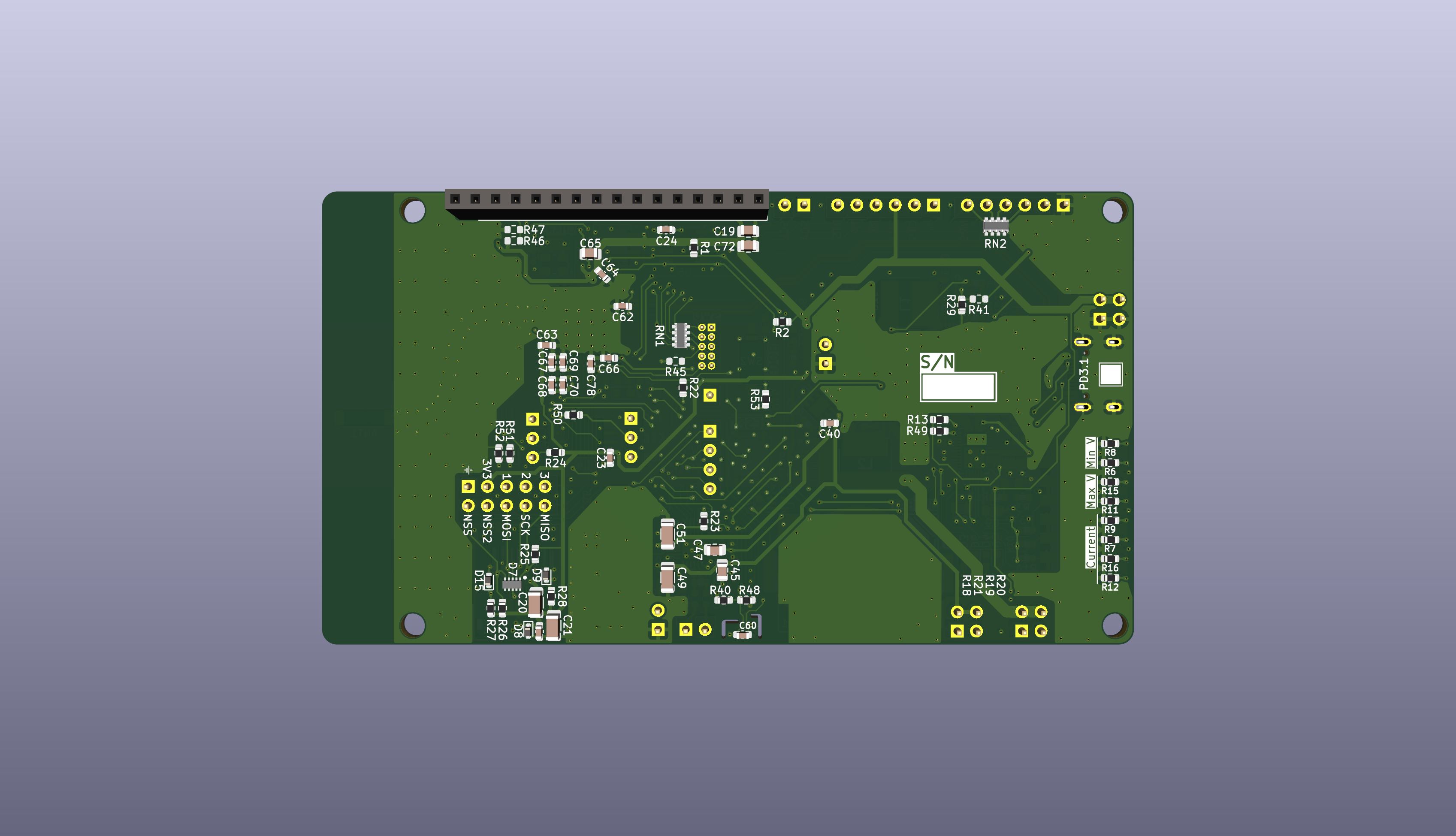
Layout of the PCB is finished! I do not expect to change very much now regarding the circuit design or changing the board in any major way. DRC check has run and there are no major issues remaining. Any additional changes should be mainly cosmetic in the PCB and organizational in the schematic files. An additional final check that could necessitate a change is to use the STM32Cube IDE to verify that the pinout for the peripherals is correct, though it was used throughout for this already. The final footprint should focus most interaction to the top of the board. For ease of mounting the referenced LCD character display to the board, a female 2.54mm socket can be attached to the back of the board and the mounting holes in the corners should be aligned so that the screen can be mounted using standoffs/screws.
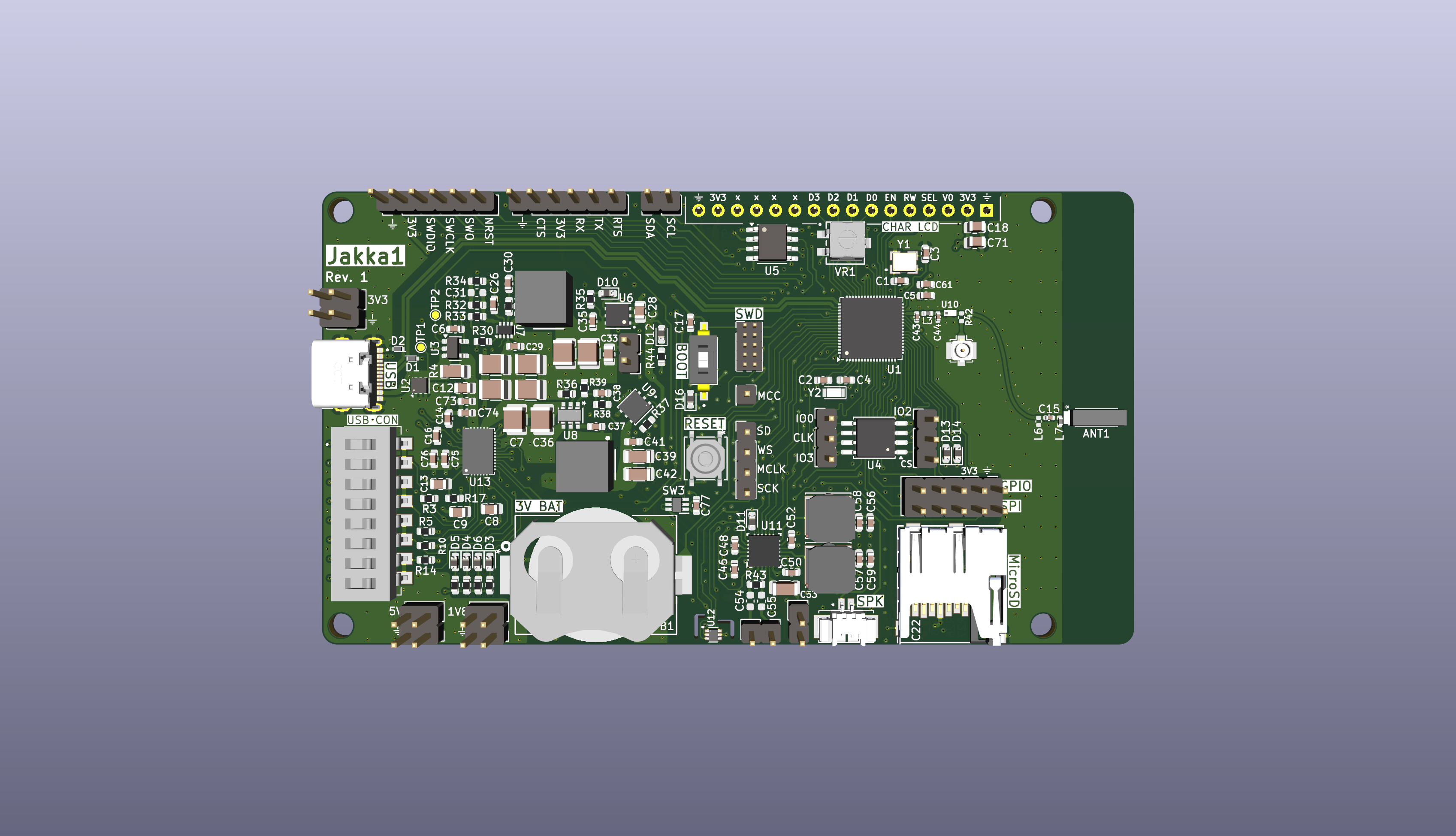
Top View
Bottom View
Layer View
The schematic should also specify all part numbers in order to generate a BOM in a future commit. Some passives and minor components remain unspecified because of their generic or non-critical parameters, e.g. specific 0603 LEDs.
The next step is to finalize the Hardware Design Output file by editing the current document to remove extra information, unused part numbers, check individual circuit blocks, part schematics, etc etc.
Layout is coming along and I am making my way to the STM32 and audio blocks. I decided to get with a ceramic chip antenna instead of the PCB antenna to increase chance of successful RF performance since I don't have RF tools right now. As such, I am using the spatial feedback of the mapped blocks to make final changes in the schematic. For example, I am most likely going to omit the onboard speaker because it really isn't necessary and I can get the version with the plug instead and use that. It looks like I will want to plan to mount the display on the bottomside of the board, otherwise I will cover any exposed pins. This requires moving the connector. Once I get that and the audio block sorted, the rest of the placement should be fairly straightforward.
Layout has started! Finally. I have made a big push to wrap up the schematic layout and do any corresponding research into the various things I wanted to study while building the board, such as RF theory, audio theory, best high-speed layout practices, EMI/EMC topics, etc etc. The schematic is largely done and should only need adjustment to address bugs or layout improvements. The layout itself is roughly mapped out and currently is sketched to support mounting the chosen LCD screen directly on top of the board, but this require sizeable footprint so I might scrap that idea as I get more blocks placed. I am currently in the stage of doing the rough placing of components relative to the center component (e.g. the STM32, USB PD chip, DC-DC regulators, audio DAC + amp, etc etc). The USB PD block is done and now I am moving on to the DC-DC converters to route power to the downstream circuitry.
| Qty | Value | Footprint | References |
|---|---|---|---|
| 21 | 100 nF | Capacitor_SMD:C_0603_1608Metric | C16, C21, C24, C25, C28, C33, C51, C53, C59, C61, C63, C65, C66, C67, C70, C71 +5 |
| 14 | 10k | Resistor_SMD:R_0603_1608Metric | R2, R3, R21, R22, R23, R27, R29, R30, R31, R32, R34, R42, R43, R49 |
| 10 | LED | Diode_SMD:D_0603_1608Metric | D3, D4, D5, D6, D11, D12, D13, D14, D15, D16 |
| 8 | 10 uF | Capacitor_SMD:C_0805_2012Metric | C1, C10, C20, C22, C45, C46, C58, C60 |
| 8 | R_US | Resistor_SMD:R_0603_1608Metric | R4, R5, R6, R7, R45, R52, R53, R54 |
| 7 | 1 uF | Capacitor_SMD:C_0603_1608Metric | C43, C44, C54, C56, C57, C73, C75 |
| 6 | 10 nF | Capacitor_SMD:C_0603_1608Metric | C2, C3, C4, C5, C68, C76 |
| 6 | 1k | Resistor_SMD:R_0603_1608Metric | R12, R19, R39, R44, R48, R51 |
| 6 | 22 uF | Capacitor_SMD:C_1206_3216Metric | C26, C27, C38, C39, C62, C64 |
| 5 | ESD321x | jka_library:SODFL1608X77N | D1, D2, D7, D8, D9 |
| 4 | 0R | Resistor_SMD:R_0603_1608Metric | R24, R35, R38, R47 |
| 4 | 10 uF | Capacitor_SMD:C_1210_3225Metric | C13, C30, C31, C41 |
| 4 | 100k | Resistor_SMD:R_0603_1608Metric | R8, R9, R10, R11 |
| 4 | 22 uF | Capacitor_SMD:C_1210_3225Metric | C11, C12, C34, C35 |
| 4 | 5.1k | Resistor_SMD:R_0603_1608Metric | R13, R14, R17, R20 |
| 4 | MountingHole | MountingHole:MountingHole_3.2mm_M3 | H1, H2, H3, H4 |
| 3 | 0.1 uF | Capacitor_SMD:C_0603_1608Metric | C29, C32, C36 |
| 3 | 4.7 uF | Capacitor_SMD:C_0805_2012Metric | C6, C7, C69 |
| 3 | 5k | Resistor_SMD:R_0603_1608Metric | R25, R26, R50 |
| 3 | Conn_01x02_Pin | Connector_PinHeader_2.54mm:PinHeader_1x02_P2.54mm_Vertical | J8, J17, J20 |
| 3 | Conn_01x03_Pin | Connector_PinHeader_2.54mm:PinHeader_1x03_P2.54mm_Vertical | J9, J18, J19 |
| 2 | 0.8 pF | Capacitor_SMD:C_0402_1005Metric | C47, C48 |
| 2 | 1 uF | Capacitor_SMD:C_0805_2012Metric | C19, C23 |
| 2 | 12 pF | Capacitor_SMD:C_0603_1608Metric | C17, C18 |
| 2 | 23.2k | Resistor_SMD:R_0603_1608Metric | R15, R18 |
| 2 | 330 pF | Capacitor_SMD:C_0603_1608Metric | C8, C9 |
| 2 | 6 pF | Capacitor_SMD:C_0603_1608Metric | C14, C15 |
| 2 | 680 nF | Capacitor_SMD:C_0603_1608Metric | C50, C52 |
| 2 | Conn_01x06_Pin | Connector_PinHeader_2.54mm:PinHeader_1x06_P2.54mm_Vertical | J11, J16 |
| 2 | EXB-38VR000V | jka_library:EXB38V472JV | RN1, RN2 |
| 2 | TestPoint | TestPoint:TestPoint_Pad_D1.0mm | TP1, TP2 |
| 2 | VLS6045AF-220M | jka_library:IND_VLS6045AF-220M | L6, L7 |
| 1 | 0 | Resistor_SMD:R_0603_1608Metric | R16 |
| 1 | 0.010R | Capacitor_SMD:C_1206_3216Metric | R1 |
| 1 | 0.3 pF | Capacitor_SMD:C_0402_1005Metric | C49 |
| 1 | 0532610271 | jka_library:MOLEX_0532610271 | J7 |
| 1 | 0R | Resistor_SMD:R_0402_1005Metric | R46 |
| 1 | 10 pF | Capacitor_SMD:C_0603_1608Metric | C42 |
| 1 | 100 pF | Capacitor_SMD:C_0603_1608Metric | C79 |
| 1 | 158k | Resistor_SMD:R_0603_1608Metric | R36 |
| 1 | 1R | Resistor_SMD:R_0603_1608Metric | R33 |
| 1 | 2.7 nH | Inductor_SMD:L_0402_1005Metric | L3 |
| 1 | 22R | Resistor_SMD:R_0603_1608Metric | R28 |
| 1 | 23BR10KLFTR | jka_library:SOT_10KLFTR_BIT | VR1 |
| 1 | 30.1k | Resistor_SMD:R_0603_1608Metric | R41 |
| 1 | 35k | Resistor_SMD:R_0603_1608Metric | R40 |
| 1 | 4-1825059-2 | jka_library:SW_4-1825059-2 | S1 |
| 1 | 47 pF | Capacitor_SMD:C_0603_1608Metric | C37 |
| 1 | 47 uF | Capacitor_SMD:C_1206_3216Metric | C55 |
| 1 | 5.6 uH | jka_library:SRP6060FA5R6M | L1 |
| 1 | 50k | Resistor_SMD:R_0603_1608Metric | R37 |
| 1 | 6.8 nF | Capacitor_SMD:C_0603_1608Metric | C40 |
| 1 | 6.8 uH | jka_library:SRP6060FA5R6M | L2 |
| 1 | 7.3 nH | Inductor_SMD:L_0402_1005Metric | L5 |
| 1 | AMCA72-2R470G-S1F-T4 | jka_library:AMCA722R470GS1FT4 | ANT1 |
| 1 | AP63300WU-7 | jka_library:TSOT6_AP63300WU-7_DIO | U7 |
| 1 | BAT-HLD-001 | jka_library:BATT_HLDR_LNX | B1 |
| 1 | CAT24C256 | Package_SO:SOIC-8_3.9x4.9mm_P1.27mm | U4 |
| 1 | Conn_01x01_Pin | Connector_PinHeader_2.54mm:PinHeader_1x01_P2.54mm_Vertical | J15 |
| 1 | Conn_01x04_Pin | Connector_PinHeader_2.54mm:PinHeader_1x04_P2.54mm_Vertical | J10 |
| 1 | Conn_01x16_Socket | Connector_PinSocket_2.54mm:PinSocket_1x16_P2.54mm_Vertical | J2 |
| 1 | Conn_02x02 | Connector_PinHeader_2.54mm:PinHeader_2x02_P2.54mm_Vertical | J4 |
| 1 | Conn_02x02_Counter_Clockwise | Connector_PinHeader_2.54mm:PinHeader_2x02_P2.54mm_Vertical | J5 |
| 1 | Conn_02x04_Odd_Even | Connector_PinHeader_2.54mm:PinHeader_2x04_P2.54mm_Vertical | J14 |
| 1 | Conn_02x05_Odd_Even | Connector_PinHeader_2.54mm:PinHeader_2x05_P2.54mm_Vertical | J12 |
| 1 | Conn_02x05_Odd_Even | Connector_PinHeader_1.27mm:PinHeader_2x05_P1.27mm_Vertical | J13 |
| 1 | Conn_Coaxial | Connector_Coaxial:U.FL_Molex_MCRF_73412-0110_Vertical | J6 |
| 1 | DLF162500LT-5028A1 | jka_library:DLF-4_1P6X0P8 | U10 |
| 1 | DS04-254-2-01BK-SMT | jka_library:DS04254201BKSMT | SW2 |
| 1 | ECS-.327-9-12R-TR | Crystal:Crystal_SMD_2012-2Pin_2.0x1.2mm_HandSoldering | Y2 |
| 1 | ECS-320-8-33B2-CTN-TR3 | jka_library:XTAL_ECS-320-8-33-RWY-TR | Y1 |
| 1 | INA180A3 | Package_TO_SOT_SMD:SOT-23-5 | U12 |
| 1 | L | Capacitor_SMD:C_0402_1005Metric | L4 |
| 1 | LD39200PU33R | jka_library:SON_DFN6_3X3_STM-L | U9 |
| 1 | LDL112PV18R | jka_library:DFN6_3P1X3P1X0P95_STM | U8 |
| 1 | MX25L12833FM2I | Package_SO:SOP-8_5.28x5.23mm_P1.27mm | U5 |
| 1 | Micro_SD_Card | jka_library:GCT_MEM2061-01-188-00-A_REVA | J3 |
| 1 | PESD3V3X4UHMYL | jka_library:SON45P80X130X43-6N | D10 |
| 1 | PTS526 SK15 SMTR2 LFS | jka_library:PTS526SK15SMTR2 LFS | SW1 |
| 1 | STM32WB55RCVx | Package_DFN_QFN:QFN-68-1EP_8x8mm_P0.4mm_EP6.4x6.4mm | U3 |
The 200 most common of 207 parts.
It measures 107.5 × 60 mm and has 4 copper layers, 1.61 mm thick.
207 parts, built around the DLF162500LT-5028A1, MX25L12833FM2I-10G, CAT24C256LI and LD39200PU33R. The full list of its parts is on this page, with links to each part's symbol and footprint where PCBKit's library has them.
From the jkapala/bleDemoPcb repository on GitHub, at the commit this page was made from: the board is ble_module.kicad_pcb and its schematic AnalogSensing.kicad_sch. PCBKit opens the board in the browser, with nothing to install.
Its repository states no licence, so its author keeps all rights: ask jkapala before reusing the design.
vasimv/Everytag
Airtag/Google FMDN tag emulation firmware, fully configurable through BLE


Batterhead221/game_girl
game_girl is a custom ESP32-S3 handheld mini-arcade built around a monochrome OLED display, rotary encoder controls, button input, buzzer audio, and battery support.

Batterhead221/pocket_sprite
A custom ESP32-S3 handheld game console with a joystick, action button, TFT display, buzzer, battery power, custom PCB, and built-in mini games.


